10 interconnection, Models 5800-s – Brooks Instrument 5800S Series User Manual
Page 16
Installation and Operation Manual
X-TMF-5800S-MFC-eng
PN 541-C-051-AAG
November, 2008
Models 5800-S
16
RxD
TxD
Gnd
3(2)
2(3)
7(5)
1
9
8
D-connector to PC
25-pin (9-pin)
15
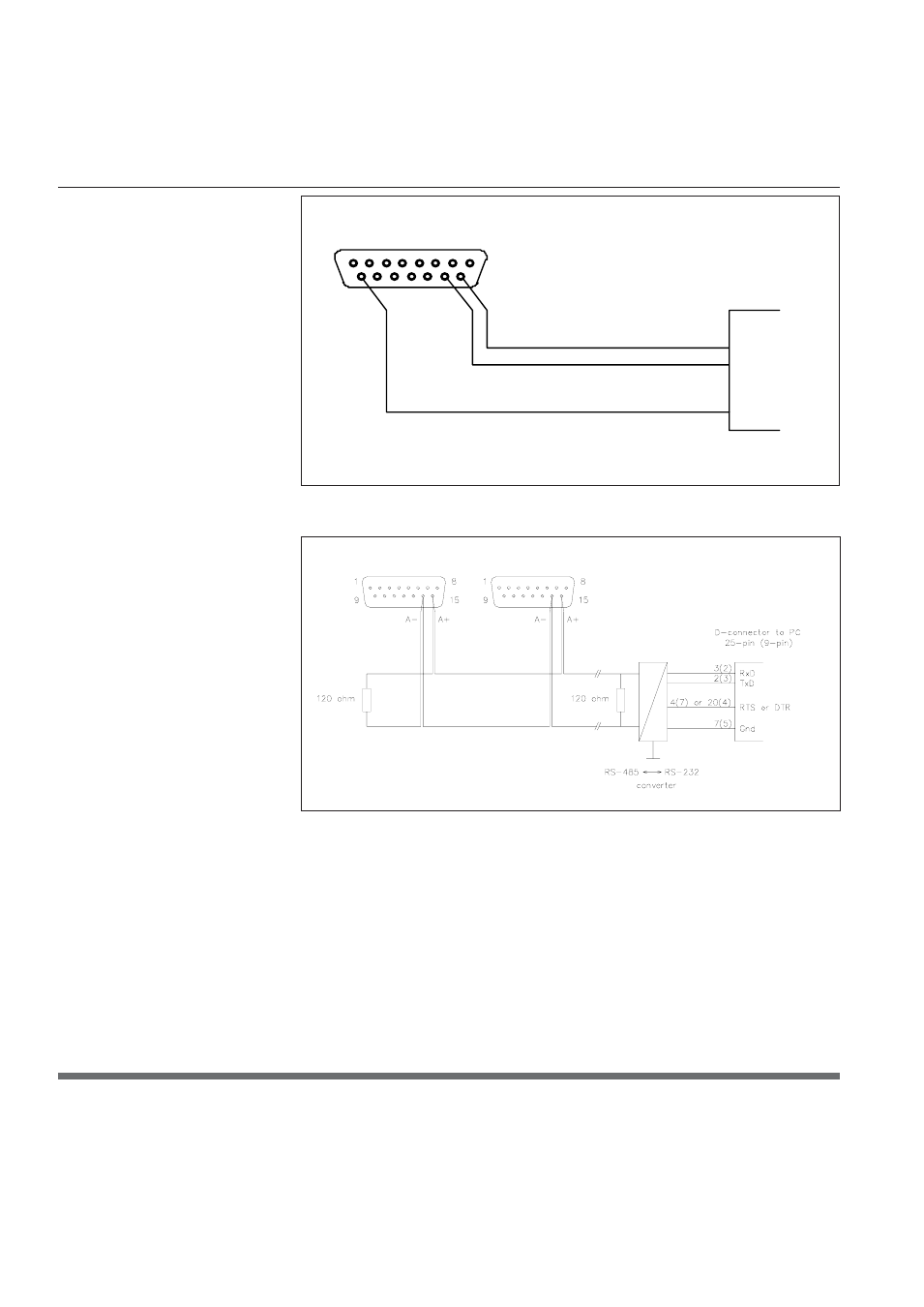
Figure 2-3: RS-232 interconnection of TMF and PC
Figure 2-4: RS-485 multidrop interconnection TMFs and PC
The RS-485 is essentially a multidrop connection. It allows a maximum of 32
devices to be connected to a computer system. IBM-ompatible PCs are not
equipped with RS-485 ports as standard. An RS-232 to RS-485 converter or
RS-485 interface board is therefore required o connect an RS-485 to a standard
PC. Figure 2-4 is an interconnection diagram showing two TMFs linked to an
IBM-compatible PC, via RS-485 and RS-485 to RS-232 converter. The RS-485
bus, a daisy-chain network, meaning that the wires are connected at the units
as in figure 2-4.
2.10 Interconnection
If no digital communication is required (i.e. analogue I/O only), the following
cables are available for connection of the Smart Mass Flow Meter/Controller to
the Brooks Microprocessor Control & Read-out Unit (see figure 2-5):
Section 2: Installation