9 digital communication, Models 5800-s – Brooks Instrument 5800S Series User Manual
Page 14
Installation and Operation Manual
X-TMF-5800S-MFC-eng
PN 541-C-051-AAG
November, 2008
Models 5800-S
14
pins 14 and 15 are available for connecting the device to the RxD/A
-
or TxD/A
+
lines for RS-232/RS-485 communications.
NOTE: Either RS-232 or RS-485 should be specified at the time of ordering. See
section 2.7 for details of how to configure the p.c. board.
2.9 Digital Communication
NOTE: The printed circuit boards only need to be reconfigured if the hardware
settings differ from those specified at the time of ordering.
Brooks Smart Mass Flow Meters and Controllers incorporate two printed
circuit boards: one main board containing the processor and a piggyback board.
The piggyback board enables the device to communicate with a PC via an
RS-232 or RS-485 connection.The piggyback board is installed via the K5, K6
and K7 connectors on the main board (see Figure 2-2).
The p.c. board enclosure must be removed to gain access to the electronics.
Disconnect the power to the device and any cables running to the D-connector.
Remove the three screws at the base of the electronics enclosure, then lift off
the enclosure. The electronics enclosure must be replaced before returning the
unit to service.
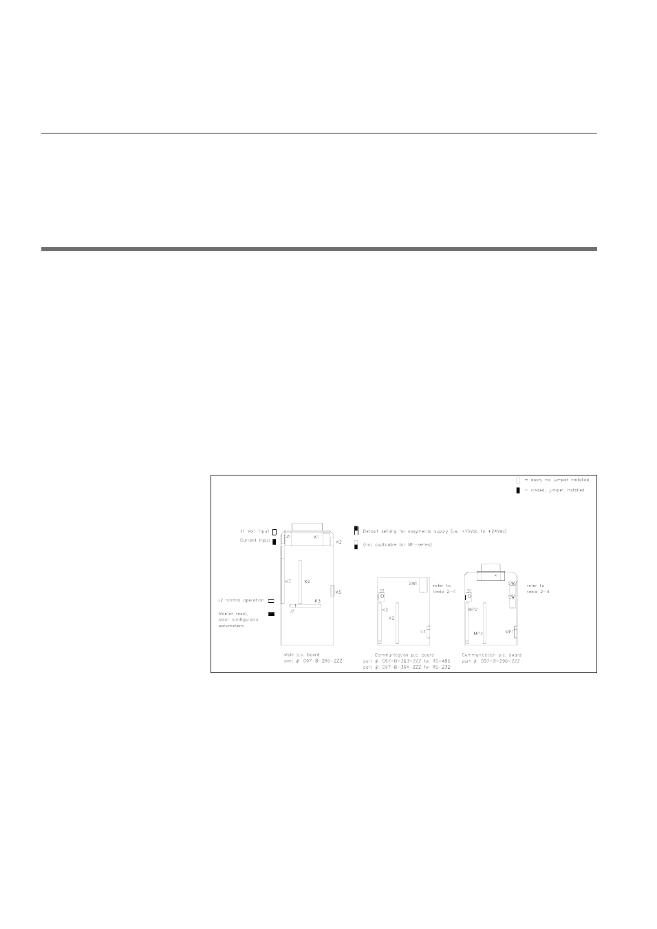
Figure 2-2: p.c. boards with the locations of jumper switches
Note: Switch number 1 is the switch at the bottom
The digital communication piggyback board is used for all
communication-related hardware settings. For this purpose, the board is
equipped with a dipswitch block (SW1) holding 4 switches. RS-232 Board
(097-B-364-ZZZ) or RS-485 Board (097-B-363-ZZZ), and to select the baud rate.
Table 2-2 summarises the possible settings.
Section 2: Installation