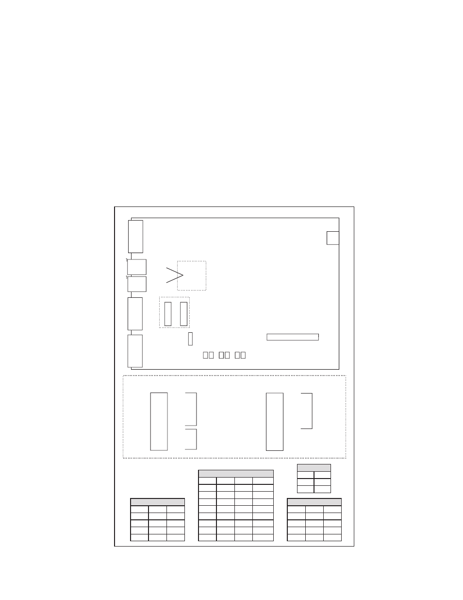
Figure 2:ts-dim main board jumper selections, Jumper detail, Top view of ts-dim main board – Franklin Fueling Systems TS-DIM User Manual
Page 6: Data bits, Baud rate, Device address, Parity
6
TS-DIM General Installation Steps – For Electronic Dispensers
1. A junction box with a single receptacle outlet must be provided (see the TS-DIM Power Requirements on page 7).
2. Securely mount the TS-DIM main box in a non-hazardous location according to the suggested layout in the Tank
Monitor Installation Instructions.
3. Referring to the connector / jumper layout diagrams that follow, verify all jumpers on the TS-DIM main board are
set according to the specific application requirements. These jumper settings have been set by the manufacturer
and should not need to be moved. Only the jumpers on SW2 may need to be adjusted depending on the
application. These jumpers allow the TS-DIM to be configured for daisy-chaining together using RS-485 multi-
drop circuitry (refer to the three diagrams in this section).
4. Plug the power adapter into the dedicated 120 VAC outlet to apply power to the TS-DIM system.
5. Connect the TS-DIM to the DBox.
6. Run internal DIM Diagnostics (Page 19), which will perform a preliminary test and gather data. Program the ATG
and refer to the TS-DIM General Installation Steps - Wiring the TS-DIM section for information on connecting a
RS232 serial port cable (field supplied) from Host1 / RS-232 on the TS-DIM to a PC.
7. Connect the TS-DIM to the ATG.
J8
AC pwr
J3
Diagnostic Port
J5 RS485 Link to next box
J4
Host1/ Rs485
Pinouts for
J4 & J5
A 1
B 3
GND 2
J2
Auxilliary/RS232
W2
1
2
3
4
5
6
7
8
W1
1
2
3
4
5
6
7
8
W3
+
-
RTS
J1
Host1/RS232
Tx Rx Tx Rx Tx Rx
Diag Host1 Aux
1 Adapter Connector
J6
W1
1
2
3
4
5
6
7
8
BR 1
BR 2
DB (7/8) Host 1
P 1
P 2
Reserved
Reserved
Reserved
Jumper Detail
W2
1
2
3
4
5
6
7
8
BR 1
BR 2
DB (7/8)
P 1
P 2
A1
A2
A3
Aux
Device
Address
Top View of TS-DIM Main Board
2 10
1 9
2 10
1 9
Data Bits
DB
0
7
1
8
Baud Rate
BR1
BR2
0
0
1200
1
0
2400
0
1
4800
1
1
9600
Device Address
A1
A2
A3
0
0
0
0/10
1
0
0
1/11
0
1
1
2/12
1
1
0
3/13
0
0
1
4/14
1
0
1
5/15
0
1
1
6/16
1
1
1
7/17
Parity
P1
P2
0
0
None
1
0
Odd
0
1
Even
1
1
N/A
Figure 2:TS-DIM Main Board Jumper Selections
Note: 1 = Jumpered
0 = No Jumper