Franklin Fueling Systems TS-DIM User Manual
Page 16
16
Pump Specific Installation — TS-DIM / T for Tokheim Electronic Dispenser
Follow the instructions in the TS-DIM General Installation section, and then do preliminary tests using the internal DIM
Diagnostics (page 19).
Install your TS-DIM and refer to the TS-DIM Adapter Board Jumper Selections Diagrams in the TS-DIM for Electronic
Dispensers, General Installation section.
1. Verify that the adapter board’s SW1 jumpers are set for Tokheim models.
2. Determine the type of electrical communications used by the Tokheim system. Match the TS-DIM with the
Tokheim system by making the corresponding jumper selections on position SW2 of the adapter board. For
Tokheim M98 and M94 Power Centers or 67 DBoxes, make the Tokheim Standard selections. For the 67B DBox,
make the RS422 / RS485 selection on position SW2.
Note: That communication for the 67 and 67B DBoxes can be modified in the field, so that model number may not
accurately reflect the communication method. Contact the Tokheim service company responsible for site service to
confirm DBox settings.
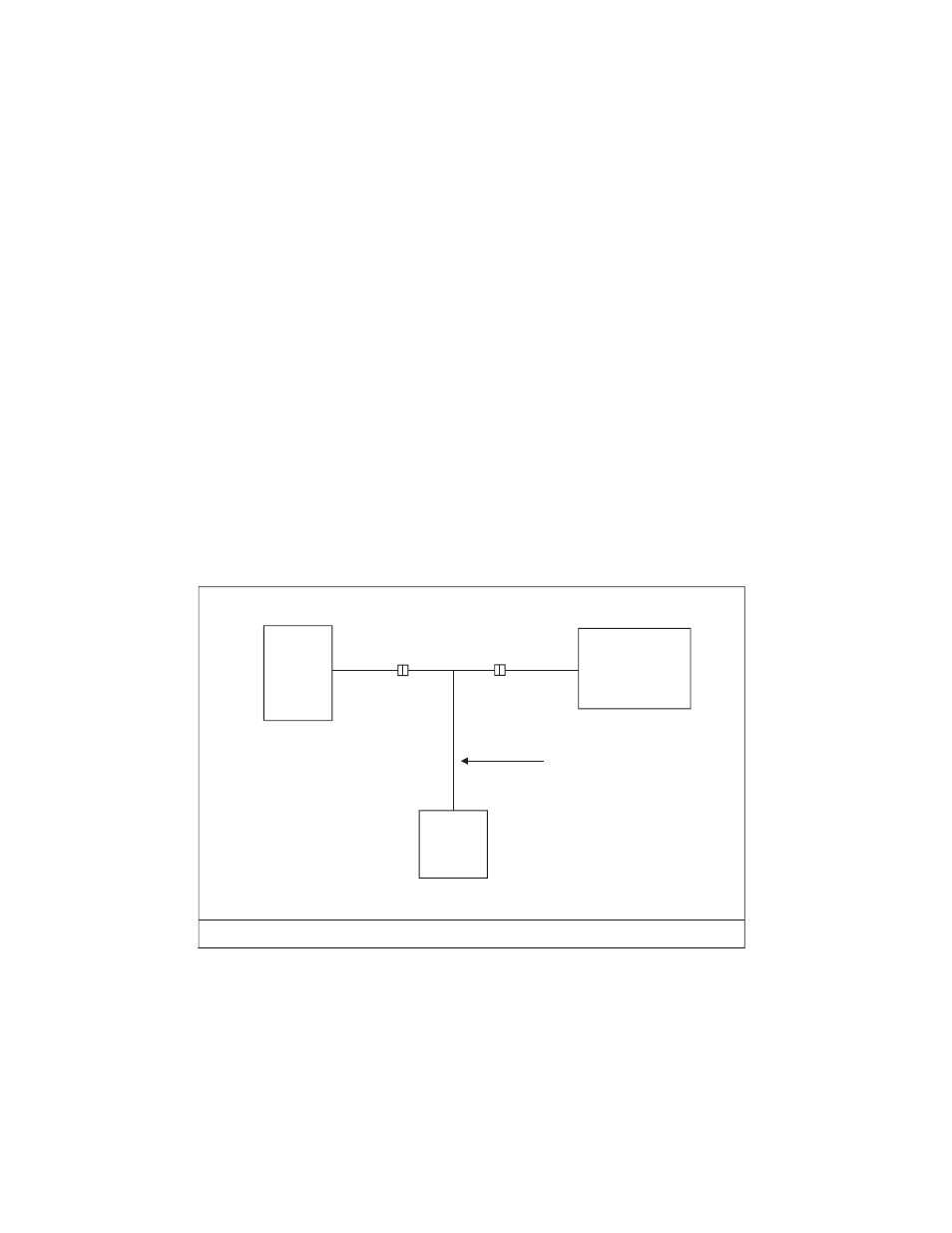
3. Plug the adapter cable (P / N 600-0204) into TS-DIM monitor cable input, and plug the adapter harness into J2 on
the adapter board.
4. Locate the round black connectors on the existing console to DBox cable. Disconnect the existing
console / controller cable from the Tokheim M98 / M94 Power Center, the 67 DBox, or the 67B DBox. Attach the
TS-DIM adapter cable to the cable ends from the console / controller and from the DBox / power center (see the
TS-DIM / T for Tokheim — Typical Installation Diagram for further information).
Tokheim 67B Note: If the cable to the controller is connected to the top board in the 67B then the comm is RS422.
If the cable is connected to the lower board in the 67B then the comm is RS232.
Program as “tokheim std” in the EMS dim programming.
Tokheim
67/67B DBox
or M94/M98
Power Center
TS-DIM/T
Tokheim
Console to Controller
TS-DIM/T Tokheim Adapter Cable
(P/N 600-0204)
TS-DIM/T to Tokheim - Typical Installation
Figure 13