General technical information – Franklin Fueling Systems TS-DIM User Manual
Page 26
26
Table 3 Gilbarco MOC G-SITE
Problem
Recommendation / Analysis
No data capture.
• Is the EMC port on G-SITE enabled?
• Is the correct software version being used on G-SITE?
• Is the adapter cable into the correct port on G-SITE?
• Is the correct type of adapter being used?
Refer to the TS-DIM Adapter Board Jumper Selections Diagram.
TS-DIM is not answering G-SITE.
• Are the settings correct on the adapter board? Refer to Figure 2 to check them.
All communications down on con-
sole / POS to pumps.
• Adapter cable not connected.
• Adapter cable connected incorrectly.
• Wrong type adapter communications input used - RS422 / current loop (refer to the TS-DIM
for Gilbarco Electronic Dispenser section of this manual).
• Defective cable.
Table 4 Tokheim
Problem
Recommendation / Analysis
Console to dispenser communi-
cation shuts down when adapter
cable is connected.
• May have wrong version adapter board in TS-DIM / T (RS422 or standard)
LEDs are off and never flash.
• Test twist-lock connectors for tightness.
• Adapter cable is connected incorrectly.
• Wrong type of adapter communications input used — RS422 / current loop. For standard
operation, connect adapter harness to J3 and place jumpers on JP1. For RS422 operation,
connect adapter harness to J2 and place jumpers on JP2.
• Defective cable.
Only one LED is flashing (D2 or D3) • Check all cable connections.
Table 5 Wayne / Dresser
Problem
Recommendation / Analysis
Data is not captured correctly for
one or more of the dispensers.
• Check both loops on the adapter cable at position J2 on the adapter board to see if they are
wired correctly.
• Check normal / bypass switch, is it Normal? See Figure 14.
Console to dispenser communica-
tion shuts down when the adapter
cable is connected.
• Adapter cable (should be in position J2) may be connected incorrectly.
• Loop wires in the DBox may be wired incorrectly (see Figure 14).
LEDs are not flashing.
• Make sure that both loops on the J2 adapter cable are wired correctly.
• Adapter cable may be connected incorrectly.
• Wrong pump type may be selected.
• Check the normal / bypass switch, is it Normal? See Figures 1 &14.
Note:
*
= With volt meter set on a 10 VDC scale, place test probes on MR line and common. With MR switch inactive
(pump off), your meter should read approximately 8 VDC. With MR switch active (pump running), your meter
should read approximately 0 VDC.
General Technical Information
This section contains miscellaneous information which may be useful in installing and troubleshooting the external TS-
DIM. Refer to the appropriate sections and diagrams in this manual for more specific information.
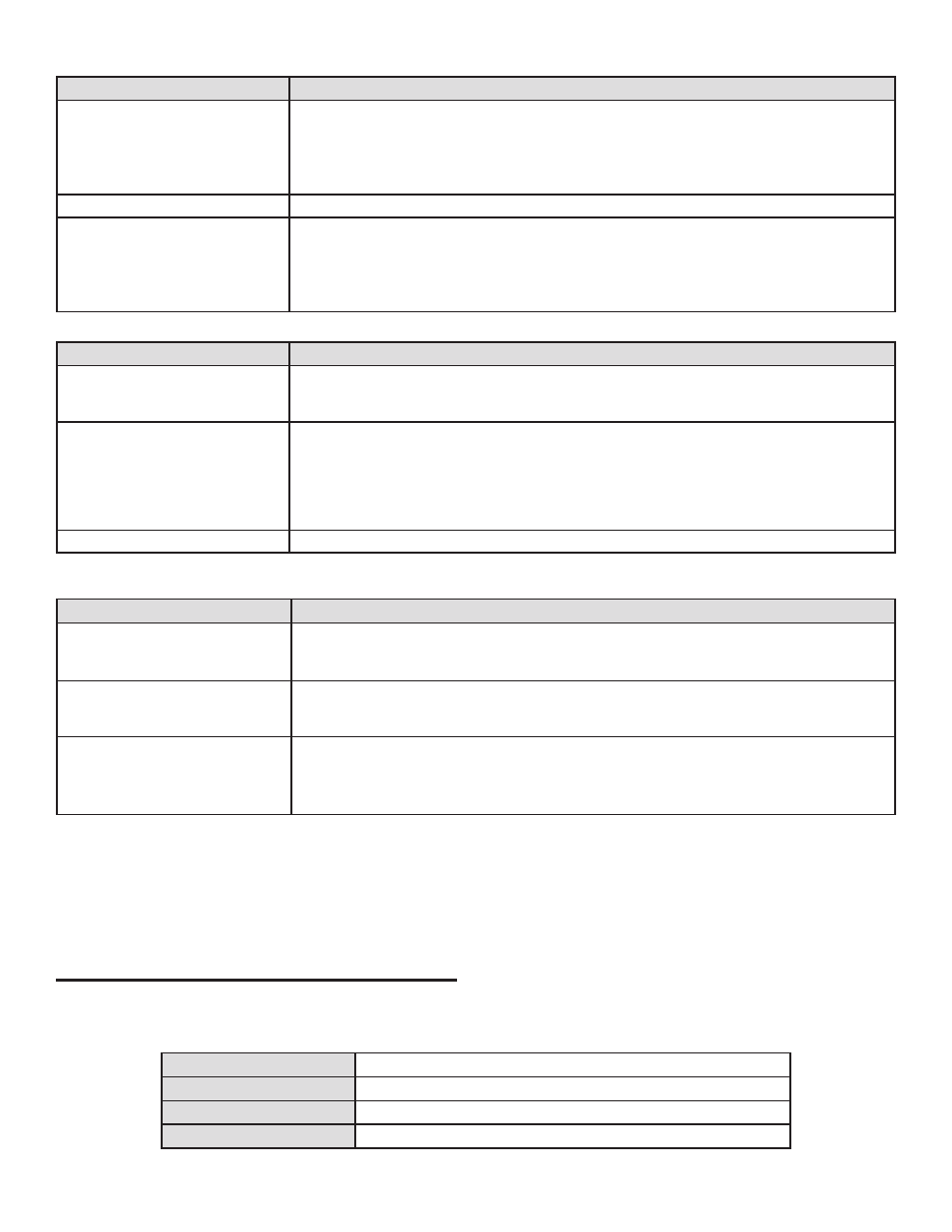
Table 8 TS-DIM General Specifications
Physical Size
7.5" x 8.5" X 2"
Operating Temperature
32 to 120 degrees F
Storage Temperature
32 to 120 degrees F
Electrical Requirements 115 VAC, 20 W Maximum (dedicated circuit with earth bond)