System installation, Description of ts-dim components, System evaluation - important site survey – Franklin Fueling Systems TS-DIM User Manual
Page 5: System installation overview, System installation requirements
5
Description of TS-DIM Components
The TS-DIM collects information on all dispensed product and consolidates the data to a concise, easy-to-read format,
facilitating the inventory reconciliation process. The TS-DIM systems are made up of the components listed below. Using
this checklist, identify and familiarize yourself with each of the components in your shipment. For further clarification, refer
to the block diagrams at the end of each section in the dispenser specific installation portion of this manual.
Note: For both the mechanical and electronic installations, the technician will need a DB9M to DB9F straight cable and a
PC to complete the installation.
Component Checklist - TS-DIM
• TS-DIM Main Box, which includes: a communication cable to the tank monitor, power transformer and a connector for
the dispenser communications adapter cable.
• Pump Communication Cable Communications Adapter Cable, which connects the TS-DIM box to the fuel dispenser or
the POS.
• Installation Manual
• System Firmware
System Installation
System Evaluation - Important Site Survey
One important step before installing the TS-DIM is to take a site
survey listing all of the fuel dispensing equipment. A site survey
should include:
• Model numbers of all dispensers and DBoxes
• Names of equipment manufacturers
• Number of dispensers
• A simple drawing showing the station layout
System Installation Overview
Install the TS-DIM system in the following order:
1. Install the controlling console and dispensers according
to the manufacturer’s specifications. Test the dispensers
with the console for proper operation. See the System
Installation Requirements section that follows for further
information.
2. Install a tank monitoring system according to the
manufacturer’s specifications. See the System Installation Requirements section that follows for further
information.
3. Mount the TS-DIM. Refer to the TS-DIM General Installation section of this manual for further information.
4. Connect the system components to the specific dispenser box (DBox). See the Pump Specific Installation section
for the appropriate brand of dispenser.
5. Test the TS-DIM with the internal Diagnostics, and map out the meters (refer to the Diagnostics section for further
information).
6. Connect to the tank monitoring system and fully test the integrated system.
System Installation Requirements
In preparation for the TS-DIM installation, ensure that the following requirements have been met.
1. Following the manufacturer’s installation instructions, install the dispensing equipment (dispensers and DBoxes).
2. Test all of the dispensers in stand-alone (manual) mode.
3. Test all of the dispensers with the same brand of console to check basic dispenser functionality and to confirm a
working communications link between the DBox and the dispensers. On dispensers which have programmable
identification numbers, ensure that the numbers are set correctly. If multiple dispensers contain the same I.D.
number, communication conflicts will occur. All dispensers and communications should function properly before
proceeding with TS-DIM installation, but, if they don’t, please contact that equipment’s vendor / manufacturer.
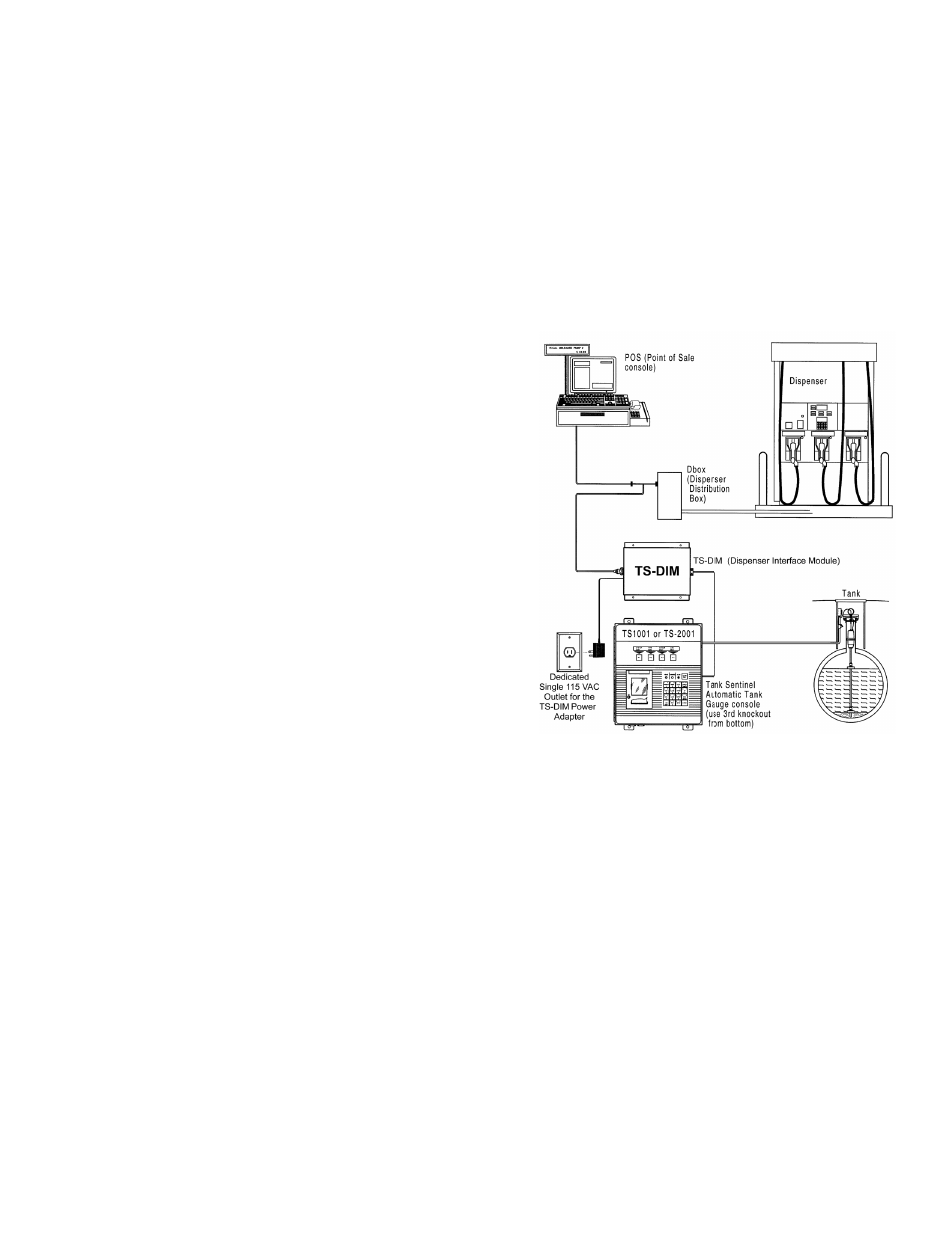
Figure 1: TS-DIM Installation Overview