Dvi input (in) – Extron Electronics VN-MATRIX User Guide User Manual
Page 101
VN-MATRIX User Guide
Section 7: Technical Data
I458GB issue 6
Page 101
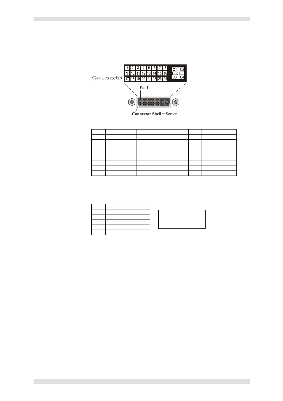
DVI Input (IN)
Function: Digital or analog video input for encoding.
Connector Type: DVI-I (female).
Pin-out Details:
Digital Connections
Pin Function
Pin Function
Pin Function
1
TMDS 2-
9
TMDS 1-
17
TMDS 0-
2
TMDS 2+
10
TMDS 1+
18
TMDS 0+
3
Ground (2/4)
11
Ground (1/3)
19
Ground (0/5)
4
nc
12
nc
20
nc
5
nc
13
nc
21
nc
6
DDC Clock
14
+5V supply*
22
Ground (Clk)
7
DDC Data
15
Ground (for 5v)
23
TMDS Clock+
8
Analog V-Sync
16
Hot Plug Detect
24
TMDS Clock-
* 5V supply is provided by VN-MATRIX and limited by 200mA polyswitch.
All ground pins are linked internally.
Analog Connections
Pin Function
C1 Red
Signal
C2 Green
Signal
C3 Blue
Signal
C4 Horizontal
Sync
C5
Ground
Mating Connector: DVI-D or DVI-I (male).
Recommended Cable: Supplied DVI cables.
Maximum Cable Length: 2.95 metres (9.5 feet).
Signal Type: DVI (PanelLink® TMDS).
Pixel Clock (DVI sources): Up to 162MHz.
Analog Sources: VGA 640x480 @ 60,72,75,85Hz
SVGA 800x600 @ 56,60,72,75,85Hz
XGA 1024x768 @ 60,72,75,85Hz
1152x864 @ 75Hz
SXGA 1280x1024 @ 60,75,85Hz
UXGA 1600x1200 @ 60Hz
Color Depth: 24-bit maximum.
Scan Mode: Progressive.
DVI Standard: DVI 1.0
Display Data Channel
Standard:
DDC2B.
DDC Levels: V
IH
= 2.4V
V
OH
= 0.9V
I
LOADMAX
= 2mA
NOTE:
Analog Vertical Sync
is on pin 8.