Extron Electronics TLP 350MV User Guide User Manual
Page 13
An Extron IP Link control interface must also be connected to the
same network domain.
are listed on page 3.
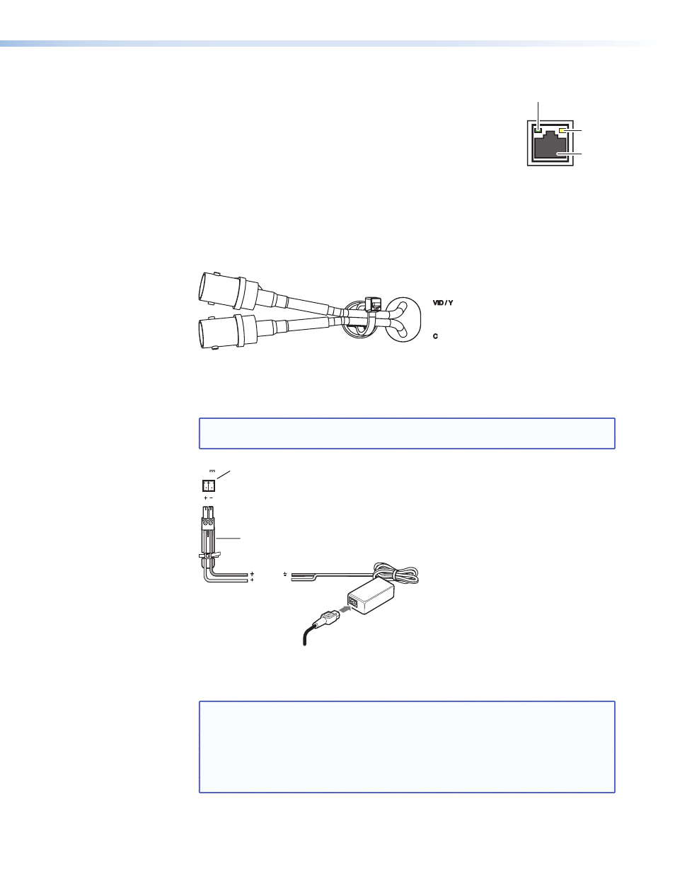
The LAN Port connector (see the figure at right) has two LED lights.
The Link LED lights green to indicate a good network connection.
The Activity LED blinks yellow when network activity occurs.
k
Video input — Connect an S-video or composite video source to the unit, using these
two BNC connectors:
For S-video, connect the Y (luminance) signal to the VID/Y input and the C
(chrominance) signal to the C input.
For composite video, connect the input to the VID/Y input.
Figure 6.
Video Input
l
Power (optional) — Extron recommends using PoE (see page 6). If a power supply is
used, two captive screw connectors accept a 12 VDC, 1.0 A input.
NOTE: If both a PoE power supply and a 12 VDC power supply are present, the unit
draws power from the PoE power supply only.
12V
1.0A MAX
POWER
Power Receptacle
DC Power Cord
Captive Screw Connector
AC Power Cord
Ground
+12 VDC
External
Power Supply
(12 VDC, 1 A )
Figure 7.
Power Connections
on page 6 for important information about power supplies.
NOTE: The length of the exposed wires in the stripping process is critical. The ideal
length is 3/16 inches (5 mm). Any longer and the exposed wires may touch,
causing a short circuit between them. Any shorter and the wires can be
easily pulled out even if tightly fastened by the captive screws.
Do not tin the wires. Tinned wire does not hold its shape and can become
loose over time.
LAN
RJ-45
Port
Link
LED
Activity
LED
LAN Port
TLP 350MV • Panels and Cabling
7