2 i/o connections, 3 connection assignment – Xylem ECOCIRC XL & XLplus User Manual
Page 21
Do not make any connection in the
pump control box unless the power
supply has been switched off for at least
2 minutes.
For models with "plug
connector" (25-40,
25-60, 32-40, 32-60).
See
.
1. Open the connector
cover and insert the
cable inside the ca-
ble gland.
2. Pull down the con-
tact retention
spring.
3. Connect the cable
according to the
wiring diagram.
4. Align the two parts
of the connector
5. Push the two parts
one inside the other.
6. Close the connector
and tighten carefully
to the cable gland.
For models with a stand-
ard terminal block con-
1. Open the terminal
box cover removing
the screws (5).
2. Use the M20 cable
gland for the power
cable.
3. Connect the cable
according to the
wiring diagram. See
.
a. Connect the ground
(earth) lead. Make
sure that the ground
(earth) lead is longer
than the phase
leads.
b. Connect the phase
leads.
4. Close the terminal
box cover and tight-
en the screws to 1
Nm.
For cable requirements, see
4.6.2 I/O connections
1. Open the terminal box cover removing the
and
2. Connect the appropriate cable according to
the terminal block diagram. See
,
and the requirements of section
3. Close the terminal box cover and tighten the
screws to 1 Nm.
4.6.3 Connection assignment
NOTICE:
• For all the connections use heat resistant cable
up to +85°C (+185°F). The cables never have to
touch the motor housing or the pump or the
pipeline.
• Wires connected to supply terminals and fault
signal relay (NO,C) must be separated from oth-
ers by reinforced insulation.
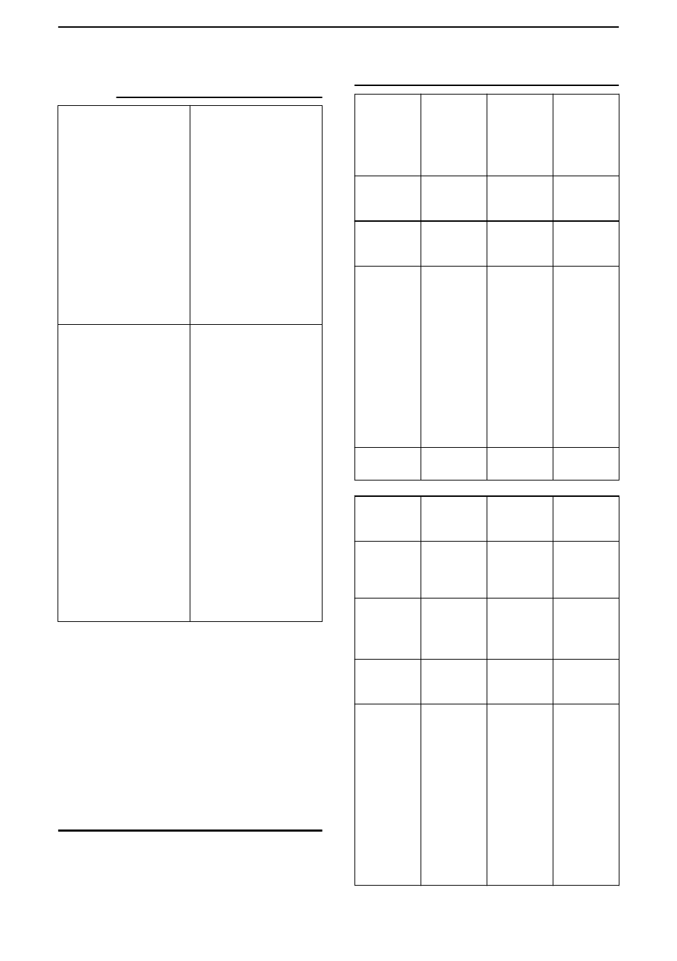
Only for
25-40,
25-60,
32-40,
32-60 Mod-
els
PLUG Con-
nector
M12 (1) Ca-
ble Φ 2÷5
mm
M12 (2) Ca-
ble Φ 2÷5
mm
Power sup-
ply
3 x
0.75÷1.5m
m
2
(2P+T)
Fault signal
2 x
0.75÷1.5m
m
2
• Analog
0-10V
• External
pres-
sure
sensor
• External
temper-
ature
sensor
• External
Start/
Stop
If NO fault
signal on
this cable
gland. Mul-
tiwire con-
trol cable,
number of
wires ac-
cording to
number of
control cir-
cuits.
Shielded if
necessary
Multiwire
control ca-
ble, num-
ber of wires
according
to number
of control
circuits.
Shielded if
necessary
Communi-
cation bus
Bus cable
M20 Cable
Φ
5÷13
mm
M16 (1)
M16 (2)
Power sup-
ply
3 x
0.75÷2.5
mm
2
(2P
+T)
- Power
supply
- Fault sig-
nal
5 x
0.75÷1.5
mm
2
(4P
+T)
Fault signal
2 x
0.75÷1.5m
m
2
• Analog
0-10V
• External
pres-
sure
sensor
• External
temper-
ature
sensor
• External
Start/
Stop
If NO fault
signal on
this cable
gland. Mul-
tiwire con-
trol cable,
number of
wires ac-
cording to
number of
control cir-
cuits.
Shielded if
necessary
Multiwire
control ca-
ble, num-
ber of wires
according
to number
of control
circuits.
Shielded if
necessary
en - Translation of the original instructions
21