GE Industrial Solutions ADVANCED SNMP WEB INTERFACE CARD User Manual
Page 22
Modifications reserved
Page 22/33
OPM_CNT_ADV_SNM_CRD_XGB_V050.doc
Operating Manual ADVANCED SNMP WEB INTERFACE CARD
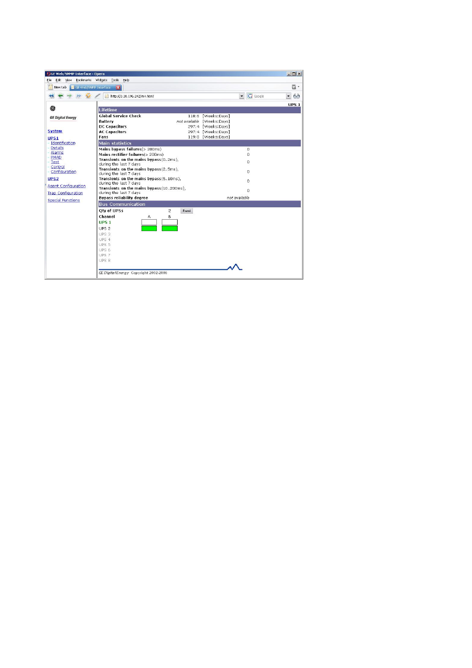
8.2.4 PMAD
web
page
Clicking on the “PMAD” page link a similar screen will appear:
Meaning of the different fields shown on the UPS Alarms page:
Lifetime
Global Service Check:
The remaining time (in [Weeks:Days]) before a general service check.
Battery:
The remaining time (in [Weeks:Days]) before a battery check.
DC Capacitors:
The remaining time (in [Weeks:Days]) before a DC capacitors check
AC Capacitors:
The remaining time (in [Weeks:Days]) before an AC output filter capacitors check
Fans:
The remaining time (in [Weeks:Days]) before a fan check
Main statistics
Mains bypass failures:
Count of main bypass failures (>200 ms), since UPS installation.
Mains rectifier failure:
Count of mains rectifier failures (>200 ms), since UPS installation.
Transients on the main bypass: Count of transients on the mains bypass (X..Y ms), during the last 7 days
Bypass reliability degree:
Bypass reliability degree [0..100%]
Bus communication
Qty of UPSs:
Number of UPSs as currently seen in the parallel system.
The reset button forces a refresh of the count and the display.
Channel table:
The table shows the actual communication status over the two redundant buses
between the unit currently selected (in green bold) and other units.
Note: The ‘Bus communication section’ is only available for single UPSs in a parallel configuration. It is
not available for stand-alone UPSs, or for the System in a parallel configuration.