Warning, Danger – GE Industrial Solutions EntelliGuard G User Manual
Page 39
DEH-41304C
EntelliGuard® G Circuit Breaker
13 March 14
Section 8 – Maintenance, Testing and Troubleshooting
©2012 General Electric All Rights Reserved
39
SECTION 8 – MAINTENANCE, TESTING AND
TROUBLESHOOTING
WARNING
IMPROPER INSTALLATION, OPERATION, SERVICE AND
MAINTENANCE
Ensure only qualified personnel install, operate, service
and maintain all electrical equipment.
Failure to comply with these instructions could result
in death or serious injury.
MAINTENANCE
DANGER
ELECTROCUTION
Ensure the circuit breaker has been tripped, indicating
OFF, and the main springs are fully discharged when
performing circuit breaker maintenance.
Failure to comply with these instructions will result in
death or serious injury.
WARNING
PERSONAL INJURY
Avoid risk of injury from moving parts while handling
the circuit breaker.
If advisable, use a cable/busbar lockable grounding
device (optional accessory) to provide additional
safety during system maintenance.
Failure to comply with these instructions could result
in death or serious injury.
Inspection Schedule
Normal working conditions:
-
Annually, or
-
Following interruption of a short circuit, or
-
After repeated high value overload faults.
Dusty/polluted environments:
-
Every six months, or
-
Following interruption of a short circuit, or
-
After repeated high value overload faults.
Cleaning Procedure
1. Inspect external surfaces for dust/dirt.
2. Clean with compressed air and dry cloth.
Contact Wear Indicator Inspection (Optional)
The contact wear indicator indicates the condition of the
contact tip when the circuit breaker is viewed in the closed
condition from the top side. It indicates the relative position
of the back edge of each contact tip with the area marked
on the wear indicator.
The back edge of each contact tip should line up with the
outer edge of the marked area on the wear indicator. As the
contacts erode, the gap between the back of the contact tip
and the rear housing becomes smaller. If the back edge of
the contact tip crosses into the marked area, the tip is
heavily eroded, and it needs to be replaced (Fig. 8.1).
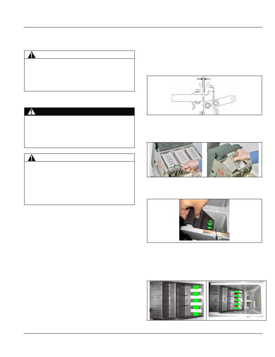
Figure 8.1. Contact Gap
Contact
gap
Contact
gap
1. Remove the arc chamber assemblies as shown in Fig.
8.2.
Figure 8.2. Arc Chamber Assembly Removal
2. Insert the wear indicator in each pole as shown in Fig 8.3.
Figure 8.3. Wear Indicator Insertion
3. View the back end of finger with the arcing contact edge
with respect to the marked area on the wear Indicator.
The marked area indicates the allowable erosion for
main tips (Fig. 8.4).
Figure 8.4. Wear Indicator in Place