GE Industrial Solutions EntelliGuard G User Manual
Page 19
DEH-41304C
EntelliGuard® G Circuit Breaker
13 March 14
Section 3 – Lifting, Mounting and Installation
©2012 General Electric All Rights Reserved
19
SECONDARY DISCONNECT BLOCKS
Located for easy customer wiring to the accessories
and to the trip unit:
-
Top-mounted for all envelopes.
-
Optional side mounting is available for UL
envelope 1.
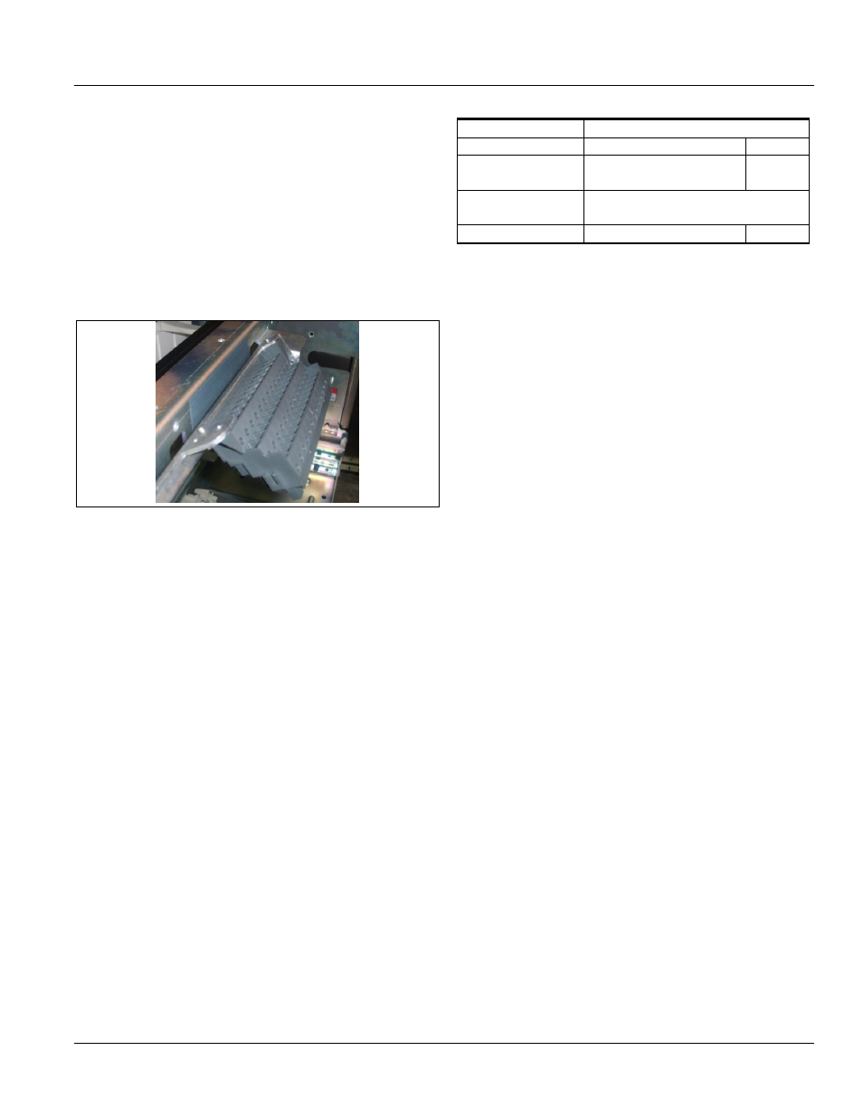
In case of drawout, by removing one screw, the
cassette-mounted secondary disconnect block can be
tilted in the mounted state and can be removed for
easy control circuit wiring (Fig. 3.24).
Figure 3.24. Secondary Disconnect
Block-A contains a set of 39 self-aligning secondary
circuit isolating contacts. Each contact is clearly
labeled with the connection point. For certain
protection configurations and additional accessories,
an additional block (Block-B) is installed.
Current rating of each terminal is 10 A/240 Vac and
5 A/250 Vdc.
Terminals are suitable for ring or spade terminals and
bare conductors (Table 3.6). Recommended max. width
or diameter of the connector is 7.4 mm.
Connector examples:
-
Ring terminals: TYCO-35684 (wire gauge 14-12)
-
Spade terminals: TYCO-34384 (wire gauge 12-10)
-
Molex-0190690230 (wire gauge 10-12)
Table 3.6. Terminal Wiring
Number of Terminals
78
Terminal capacity
1x
2x
Screw type (bare
conductors)
12 AWG,
solid or stranded
-
Screw type (bare
conductors)
22 AWG to 14 AWG,
0.5 mm² to 2.5 mm²
Ring/spade terminals
20 AWG to 12 AWG
-
SELECTIVITY/BACKUP PROTECTION
The circuit breaker is time-selective with the
downstream ACB and MCCBs up to the lowest of the
breaking capacity of the combination.
Selectivity levels are determined by the selection
settings of short time and instantaneous pickup and
time delay on the Trip Unit.
No backup protection/cascading (series ratings) is
available with this product.