Danger – GE Industrial Solutions EntelliGuard G User Manual
Page 15
DEH-41304C
EntelliGuard® G Circuit Breaker
13 March 14
Section 3 – Lifting, Mounting and Installation
©2012 General Electric All Rights Reserved
15
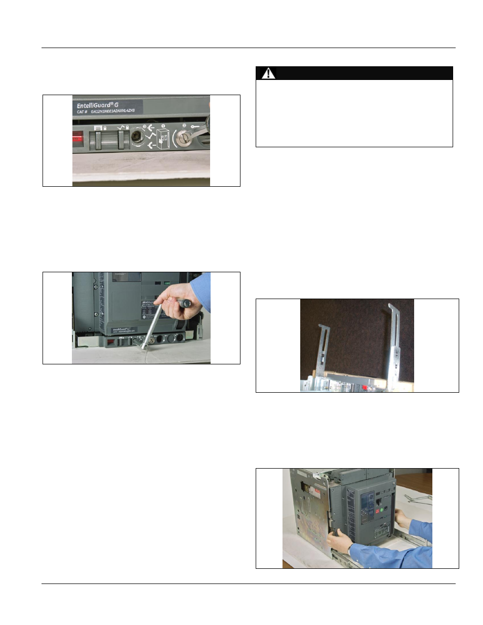
13. With a screwdriver, turn the racking handle shutter
drive A clockwise (Fig. 3.14).
Figure 3.14. Racking Handle Shutter Drive Location
14. Insert the racking handle in the handle insertion hole
on the cassette front panel.
15. Rotate clockwise to rack the circuit breaker into the
cassette. As the breaker approaches the TEST position
check the alignment of the fixed and moving parts of
the secondary circuit isolating contacts (Fig. 3.15).
Figure 3.15. Turning the Racking Handle
16. Continue rotating the racking handle clockwise until
the position indicator first shows TEST, then
CONNECTED. When approaching the CONNECTED
position, effort to turn the racking handle will increase
as the clusters engage with the cassette-mounted
contacts. If a motor spring charge or under voltage to
release is installed, these may operate when
approaching the TEST position.
17. Remove and store the racking handle in its storage
location.
18. The circuit breaker is now ready for normal operation.
Circuit Breaker Removal from the Cassette
DANGER
ELECTROCUTION
Ensure the circuit breaker has been tripped, indicating
OFF, and the main springs are fully discharged.
Do not touch the circuit breaker’s isolating contacts
during lifting.
Failure to comply with these instructions will result in
death or serious injury.
1. Repeat Steps 10 through 13 as explained in the previous
section. Insert the racking handle in the handle insertion
hole on the cassette front panel
2. Rotate counter clockwise to rack the circuit breaker out
of the cassette. As the circuit breaker approaches the
TEST position, check the alignment of the fixed and
moving parts of the secondary circuit isolating contacts.
3. Continue rotating the racking handle counter clockwise
until the position indicator first shows TEST, then
DISCONNECTED.
4. Pull out the cassette rails until they drop into the
horizontal locked position (Fig. 3.16).
Figure 3.16. Cassette Rails Pulled Out for Circuit Breaker
Unloading
5. Using the hand grips on either side, pull the circuit
breaker out of the cassette until it reaches a positive
stop (rollers on the circuit breaker will stop against the
extended rail projection as shown in Fig. 3.17).
Figure 3.17. Circuit breaker Pulled Out of the Cassette for
Unloading