GE Industrial Solutions EntelliGuard G User Manual
Page 28
EntelliGuard® G Circuit Breaker
DEH-41304C
Section 6 – Accessories Description
13 March 14
28
©2012 General Electric All Rights Reserved
Circuit Breaker Closing Coils – Standard and Commanded
Two, easy-to-fit, clip-on closing coil options with simple,
plug-in connections are available. Both options offer
electrical remote release of the spring charged closing
mechanism. Both options include a standard anti-pump
safety feature ensuring that the remote signal must be
released before further close commands are allowed. The
Command Close Coil additionally provides for local
electrical command of the accessory and remote
command over communications via the EntelliGuard trip
unit (Table 6.2).
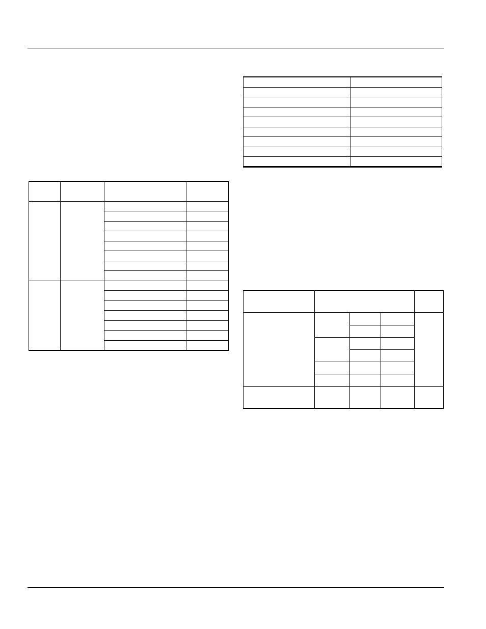
Table 6.2. Closing Coil Characteristics
Type
Power
Consumption
Nominal Control
Voltage
Catalog
Number
Closing
Coil
DC: 350 W,
20 W (sealed)
AC: 350 W
(inrush),
20 W (sealed)
24/30 Vdc
GCCN24DR
40 Vdc; 48 Vac/dc
GCCN048R
60Vdc
GCCNM060DR
70 to 72 Vac/Vdc
GCCN072R
110/130/120 Vac
GCCN120R
208 Vac
GCCN208AR
220 Vdc/240 Vac
GCCN240R
250 Vdc/277 Vac
GCCN277R
Command
Operated
Closing
Coil
DC: 350 W,
20 W (sealed)
AC: 350 W
(inrush),
20 W (sealed)
24/30 Vdc
GCCC24DR
40 Vdc; 48 Vac/dc
GCCC048R
60 Vdc
GCCCM060DR
70 to 72 Vac/Vdc
GCCC072R
110/130/120 Vac
GCCC120R
208 Vac
GCCC208AR
220 to 250 Vac/Vdc/249 Vac
GCCC240R
Duty cycle = 2/min.
Closing coil inrush = 350 VA.
Command Operation Module
This module energizes the closing coil to cause the breaker
to close whenever control power is applied to the
accessory and when commanded from the breaker trip
unit or breaker front panel push button (electrical closing).
Shunt Trip (ST)
Energizing the shunt trip, via local or remote input, will
instantaneously activate the circuit breaker mechanism,
ensuring a rapid open operation. The standard auxiliary switch
ensures automatic isolation whenever the circuit breaker is
open. The shunt trip release is a straightforward, field installable
accessory available in wide range of voltages (Table 6.3).
Table 6.3. Extended Range Shunt Trip for UL Ground Fault
and ANSI DC Rating Applications.
Nominal Control Voltage
Catalog Number
24 Vdc
GSTG024DR
48 Vac/dc
GSTG048R
70/72 Vdc
GSTG072DR
110 Vdc/120 Vac
GSTG120R
125 Vdc
GSTG125DR
208 Vac
GSTG208AR
240 Vac
GSTG240R
250 Vdc/277 Vac
GSTG277R
Pickup range = 55%-110%.
Duty cycle = 2/min.
Inrush = 480 A (ac), 480 W (dc).
Holding = 60 VA (ac), 50 W (dc).
Status Indication Switch (Coil Signaling Contact)
A plug-in module is available to provide status indication via
the secondary disconnects and trip unit. Coil Signaling
Contacts are available for closing coils, shunt trips and under
voltage releases, see Table 6.4. Contac t is mounted on top of
the Accessory Device.
Table 6.4 Coil Signaling Contact Module
Type and
Configuration
Rating
Cat. No.
1 Power rated +
1 Low signal (Hi-Fi)
(1NO contact each)
AC
120 Vac
6 A
GCSP1R
250 Vac
6 A
DC
125 Vac
0.5 A
250 Vdc
0.25 A
AC
125 Vac
0.1 A
DC
30 Vdc
0.1 A
2 Low signal (Hi-Fi)
(1NO contact each)
AC
125 Vac
0.1 A
GCSP2R
Under Voltage Release (UVR) With Fixed Time Delay
The UVR instantaneously activates the circuit breaker trip
mechanism when the source voltage drops below the low
voltage threshold. The UVR is also a simple, field installable
device. NOTE: This accessory acts as a permissive; it is a no-
voltage/no-close device. The circuit breaker cannot be closed
(manually or electrically) unless the under voltage release coil
is energized above the required threshold. The UVR shunt trip
with fixed time delay is specifically intended for applications
where a delay period (ride-through) is required due to
potential voltage events. The delays are 50 ms when system
voltage drops to 50% and 20 ms when system voltage drops
below 50%. See Table 6.4. (A Time Delay Module is also
available, see next page).