GE Industrial Solutions EntelliGuard G User Manual
Page 37
DEH-41304C
EntelliGuard® G Circuit Breaker
13 March 14
Section 7 – Accessories Installation
©2012 General Electric All Rights Reserved
37
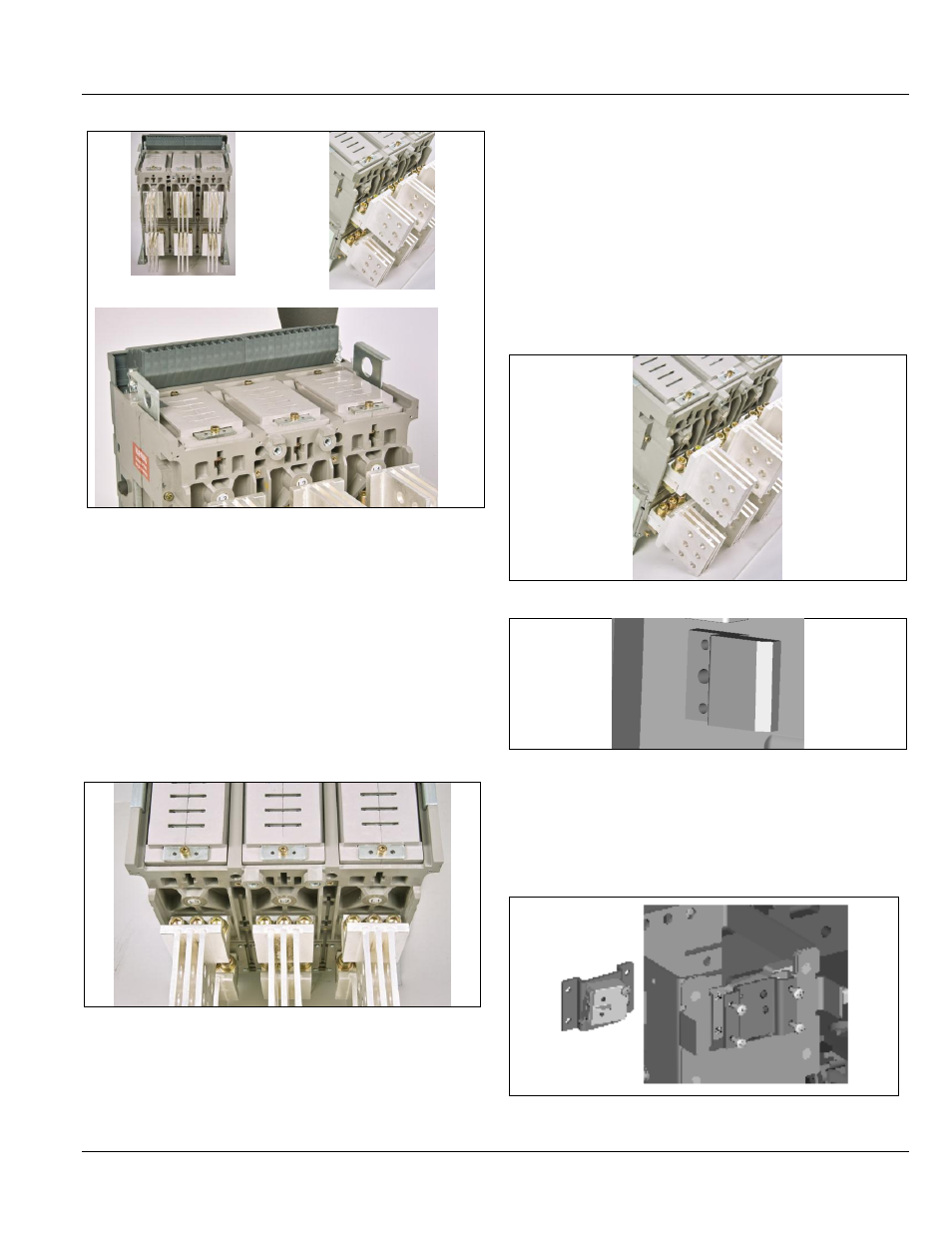
Figure 7.13. Cluster Views
Upper Cluster Contact Grounding
1. Using the cluster pliers, remove the upper cluster
contacts the rear of the circuit breaker.
2. Position the grounding bar on the exposed top of the
top terminals, ensuring the spring-loaded grounding
contact is facing left when viewed from the rear.
3. Install bolts and washers using the threads in the
grounding bar, one bolt per pole. Torque to 30 N m.
4. The spring loaded grounding contact will engage with
the top fixed grounded contact block in the cassette
when the breaker is racked to the CONNECTED position
(Fig 7.14).
Figure 7.14 Cluster Contact Grounding Top Location
Lower Cluster Contact Set Grounding (Figs. 7.15 and 7.16)
1. Using the cluster pliers, remove the lower cluster
contacts at the rear of the circuit breaker.
2. Position the grounding bar on the exposed top of the
bottom terminals, ensuring the spring-loaded grounding
contact is facing left when viewed from the rear
3. Install bolts and washers using the threads in the
grounding bar, one bolt per pole. Torque to 30 N m.
4. The spring loaded grounding contact will engage with
the bottom fixed grounded contact block in cassette
when the breaker is racked to the CONNECTED position.
Figure 7.15. Cluster Contact Grounding Top Location
Figure 7.16. Fixed Grounding Contact in Cassette
MECHANICAL TRIP ALARM INSTALLATION
1. Remove the front cover.
2. Remove the trip unit.
3. Install the mechanical trip alarm as shown in Fig. 7.17.
Figure 7.17. Mechanical Trip Alarm