GE Industrial Solutions EntelliGuard G User Manual
Page 18
EntelliGuard® G Circuit Breaker
DEH-41304C
Section 3 – Lifting, Mounting and Installation
13 March 14
18
©2012 General Electric All Rights Reserved
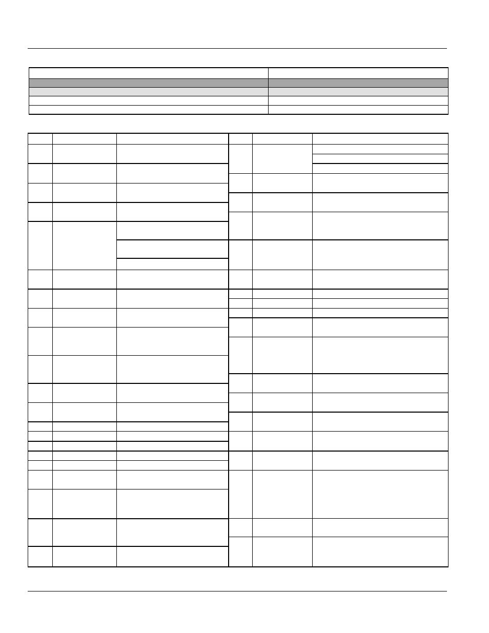
Table 3.4. Electronic Interlock
Network Interlock Connections
Network Interlock Status Switch
A5
A6
A7
A8
B4
B5
B6
NI TRIP
NI TRIP
NI RESET
NI RESET
NI NC
NI NO
NI COM
1.9 A
1.9 A
1.9 A
1.9 A
10 A
10 A
10 A
240 V
240 V
240 V
240 V
240 V
240 V
240 V
Table 3.5. Wiring Schematic Nomenclature Definitions
Pin
Nomenclature
Description
Pin
Nomenclature
Description
A1
Motor
power input to motor operator
B1
Input 1
relay input to trip unit
A2
Motor
B2
Input 2
relay input to trip unit
A3
SPR NO/RTC NO
spring charge status contact/
ready to close signaling contact
B3
I/P COM
relay input to trip unit
A4
SPR NO/RTC NO
B4
ST1 NO/NC8
shunt trip 1 signaling contact/normally
open contact 8
A5
ST1
power input to shunt trip 1
B5
ST1 COM/NC8
A6
ST1
B6
UV1 NO/NC7
under voltage release 1 signaling
contact/normally closed contact 7
A7
UV1
under voltage release 1
B7
UV1 COM/NC7
A8
UV1
B8
NC6
normally closed contact 6
A9
CC COM
closing coil neutral wire-common
(CC or CCC)
B9
NC6
A10
CC IMM
closing coil (CC), continuous
control power (CCC)
B10
NC5
normally closed contact 5
A11
CC CMD
closing coil close signal (CCC)
B11
NC5
A12
ST2/UV2
power input to shunt trip 2/under
voltage release 2
B12
NC4
normally closed contact 4
A13
ST2/UV2
B13
NC4
A14
NC3
normally closed contact 3
B14
RELT
RELT signal output
A15
NC3
B15
COM
trip unit communication
A16
NC2
normally closed contact 2
B16
-
-
A17
NC2
B17
CC NO/NO8
closing coil signaling contact/normally
open contact 8
A18
NC1
normally closed contact 1
B18
CC COM/NO8
A19
NC1
B19
ST2 NO/UV2
NO/NO7
shunt trip 2 signaling contact/under
voltage release 2 signaling contact/
normally open contact 7
A20
NO3
normally open contact 3
B20
ST2 COM/UV2
COM/NO7
A21
NO3
B21
NO6
normally open contact 6
A22
NO2
normally open contact 2
B22
NO6
A23
NO2
B23
NO5
normally open contact 5
A24
NO1
normally open contact 1
B24
NO5
A25
NO1
B25
NO4
normally open contact 4
A26
-
-
B26
NO4
A27
O/P1a
relay output 1 from trip unit
B27
ZSI out+
GF zone selective interlock output
A28
O/P1b
relay output 1 from trip unit
B28
ZSI out-
A29
O/P2a
relay output 2 from trip unit
B29
ZSI in+
GF zone selective interlock input
A30
O/P2b
relay output 2 from trip unit
B30
ZSI in-
A31
24 V+
auxiliary power supply to trip unit
B31
ISO GND
trip unit communication
A32
24 V-
B32
5V Iso
A33
BA NC
bell alarm switch
B33
TX EN 1
A34
BA NO
B34
RX
A35
BA COM
B35
TX
A36
N-RC-
neutral Rogowski coil
B36
Voltage Input
GND
ground point for voltage input to trip unit
A37
N-RC+
B37
Volt-A
system phase voltage signals
A38
Eleg-CT
earth leg CT (multi-source ground
fault)
B38
Volt-B
A39
Eleg-CT
B39
Volt-C