Warning, Caution, Notice – GE Industrial Solutions EntelliGuard G User Manual
Page 20
EntelliGuard® G Circuit Breaker
DEH-41304C
Section 4 – Operation
13 March 14
20
©2012 General Electric All Rights Reserved
SECTION 4 – OPERATION
WARNING
IMPROPER INSTALLATION, OPERATION AND
MAINTENANCE
Ensure only qualified personnel install, operate, service
and maintain all electrical equipment.
Failure to comply with these instructions will result in
death or serious injury.
WARNING
PERSONAL INJURY
Avoid risk of injury from moving parts while handling
the breaker.
If advisable, use a cable/busbar lockable grounding
device (optional accessory) to provide additional safety
during system maintenance.
Failure to comply with these instructions could result in
death or serious injury.
CAUTION
PRODUCT DAMAGE
Ensure circuit breaker and its accessories are always
used within their designated ratings.
Use the specially designed circuit breaker handling
truck (optional accessory) when removing the circuit
breaker from its cassette.
Failure to comply with these instructions may result in
product damage.
STORED ENERGY MECHANISM KEY FEATURES (Table 4.1)
NOTICE
Each charging action provides sufficient charge for an
O-C-O (Open-Close-Open) operation without requiring
additional charging.
The mechanism works properly only when the circuit
breaker is mounted on a horizontal plane with bottom
mounting or on vertical plane with front mounting.
Circuit Breaker Charging
The circuit breaker can be charged in one of two ways:
Manually, using a charging handle.
-
The charging handle lies flush within the circuit
breaker front cover. It is easily retracted without
special tools.
-
Full spring charging is accomplished with 10 full
pumps or less of the handle. Handle movement
includes suitable stops so that it cannot be over
extended and cause operator injury.
-
The handle engages the charging ratchet during
motion away from the circuit breaker front cover
and rotates freely on the return stroke.
Electrically, via a motor operator that is automatically
activated after the closing operation.
Two Step Mechanism Design
The first step charges the closing spring through the
manual charging handle or through the spring
charging motor.
The second step closes the circuit breaker via the
PUSH ON (UL)/CLOSE (ANSI) pushbutton on the front
cover or closes the breaker through energizing the
closing coil.
The mechanism is trip free and incorporates an anti-
pumping system:
-
The circuit breaker may be closed only after the
mechanism is fully charged and there is no active
open command.
-
The closing coil has an electrical anti-pumping
feature. The coil supply, if maintained
continuously, will attempt to close the circuit
breaker only one time. To achieve a second
closing attempt, the closing coil must be de-
energized and energized a second time.
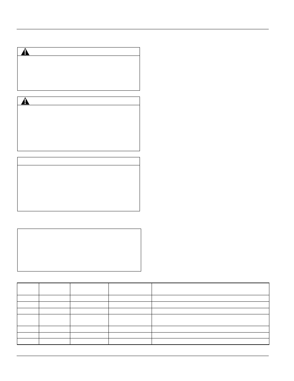
Table 4.1. Stored Energy Mechanism Sequences of Operation
ON/OFF
Indicator
Main Breaker
Contacts
Charging Spring
Indicator
Condition of
Charging Springs
Next Permissible Operating Function
OFF
open
discharged
discharged
closing springs may be charged
OFF
open
charged
fully charged
contacts may be closed, then opened
ON
closed
discharged
discharged
contacts may be opened or closing springs may be charged
ON
closed
charged
fully charged
pen-closed-open sequence may be carried out and the closing
springs can be charged after the close operation opened
OFF
open
charged
fully charged
closing spring may be discharged without closing contacts
ON
closed
charging
partially charged
complete charging
OFF
open
charging
partially charged
complete charging