Notice, Danger – GE Industrial Solutions EntelliGuard G User Manual
Page 35
DEH-41304C
EntelliGuard® G Circuit Breaker
13 March 14
Section 7 – Accessories Installation
©2012 General Electric All Rights Reserved
35
5. Use an M8 nylock nut to mount the motor switch
actuator onto the shaft end, torque to 14.5 N m.
6. Connect the motor connector on to the motor harness.
7. Connect the remaining ground wire from the filter to
the grounding point on the rear of the motor body.
Reverse the above procedure to remove the motorized
spring charging unit
SHUNT TRIP, CLOSING COIL AND UNDER VOLTAGE
RELEASE DEVICE INSTALLATION
NOTICE
The mounting positions of the four devices can be
arranged in the locations as specified in Figure 7.4.
Figure 7.4. Device Location
Combi-
nation
Coil Position on Fascia
1
Network
(IEC)
Interlock
(IEC)
closing coil
under
voltage
2
shunt
shunt
closing coil
under
voltage
3
shunt
UV
closing coil
under
voltage
4
network
under
voltage
closing coil
shunt
Closing Coil Installation (Fig. 7.5)
1. Tilt the device forward and engage the front hooks into
the top support plate.
2. Tilt the device backwards until the rear hooks engage
in the slots
3. Press down into position.
Figure 7.5. Closing Coil Installation
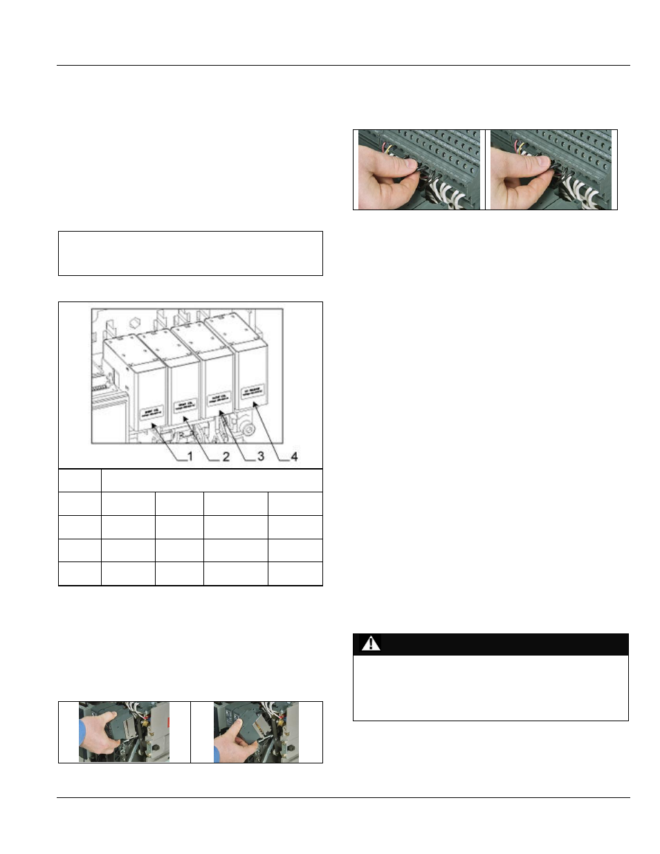
Connect the wire plugs (Fig. 7.6) according to the wiring
schematic in Section 3.
Figure 7.6. Wiring
Closing Coil Removal
1. Disconnect the device and tilt it forward until the rear
hooks disengage.
2. Lift to release the front hooks.
NETWORK INTERLOCK INSTALLATION
When the network interlock is used with the EntelliGuard G,
it will use the C and D positions of the coils as shown in Fig.
7.4. The mounting procedure is same as the coils.
Trip Alarm/Bell Alarm Switch Installation
1. Remove the 40 pin harness (if installed) from the trip unit.
2. Remove the trip unit from the PMU base.
3. Assemble the trip alarm assembly as shown using four
screws.
4. Reassemble the trip unit back on to the PMU base
5. Install the connector from the trip alarm in the specified
location of the SD.
6. Reassemble the 40 pin harness.
Ready to Close Switch Installation
1. Slide the RTC switch assembly on to the mechanism side
sheet.
2. Assemble the screw and washer.
3. Assemble the snap-on connector to make the electrical
connection.
4. Using the cable tie, tie the wires to the PMU base.
SHUTTER PROP OPEN FEATURE
This feature allows the main fixed contacts to be inspected.
DANGER
ELECTROCUTION
Ensure the fixed contacts on the incoming side are isolated
prior to installing the Shutter Prop Open Feature.
Failure to comply with these instructions will result in
death or serious injury.