Danger, Warning, Caution – GE Industrial Solutions EntelliGuard G User Manual
Page 34
EntelliGuard® G Circuit Breaker
DEH-41304C
Section 7 – Accessories Installation
13 March 14
34
©2012 General Electric All Rights Reserved
SECTION 7 – ACCESSORIES INSTALLATION
DANGER
ELECTROCUTION
Ensure the circuit breaker has been tripped, indicating
OFF, and the main springs are fully discharged before
installing accessories.
Failure to comply with these instructions will result
in death or serious injury.
WARNING
IMPROPER INSTALLATION, OPERATION AND
MAINTENANCE
Ensure only qualified personnel install, operate, service
and maintain all electrical equipment.
Failure to comply with these instructions could
result in death or serious injury.
WARNING
PERSONAL INJURY
Avoid risk of injury from moving parts while
handling the breaker.
If advisable, use a cable/busbar lockable
grounding device (optional accessory) to provide
additional safety during system maintenance.
Failure to comply with these instructions could
result in death or serious injury.
CAUTION
PRODUCT DAMAGE
Ensure circuit breaker and its accessories are
always used within their designated ratings.
Use the specially designed circuit breaker handling
truck (optional accessory) when removing the
circuit breaker from its cassette.
Failure to comply with these instructions may result
in product damage.
CIRCUIT BREAKER FRONT COVER REMOVAL
Required for most accessory installation.
1. Remove the six mounting screws (Fig. 7.1).
Figure 7.1. Front Cover
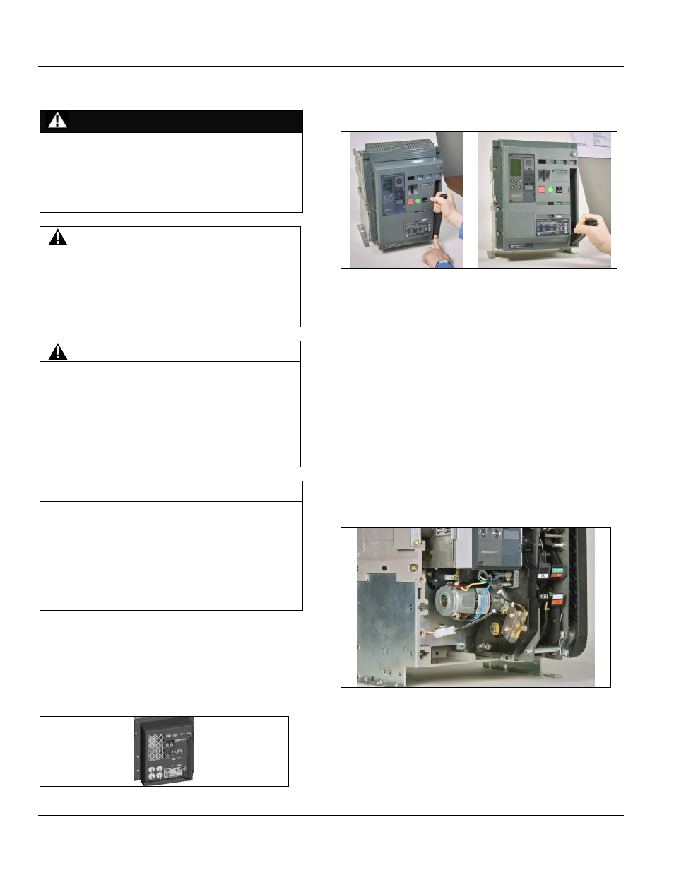
2. Pull the charging handle while easing the cover
upwards (Fig. 7.2).
Figure 7.2. Charging Handle Position for Cover Removal
MOTOR OPERATOR - SPRING CHARGING UNIT
INSTALLATION
1. Slide the coupling bushing on to the camshaft.
2. Place the gearbox bearing on to the protruding motor
drive shaft, pushing it home until flush with the
mechanism sideplate. If it does not move easily to the
flush position, pull the charging handle gently down to
ease movement.
3. Mount the device using three M5 bolts through the
holes provided in the gearbox endplate, torque to
7 N m.
4. Manually charge the closing springs and carefully locate
the plastic switch actuator over the protruding drive
shaft (Fig. 7.3), ensuring the switch operating arm is
correctly positioned (switch arm should be in the ‘cut
out’ portion of the motor switch actuator.
Figure 7.3. Motor Switch Actuator