GE Industrial Solutions EntelliGuard G User Manual
Page 31
DEH-41304C
EntelliGuard® G Circuit Breaker
13 March 14
Section 6 – Accessories Description
©2012 General Electric All Rights Reserved
31
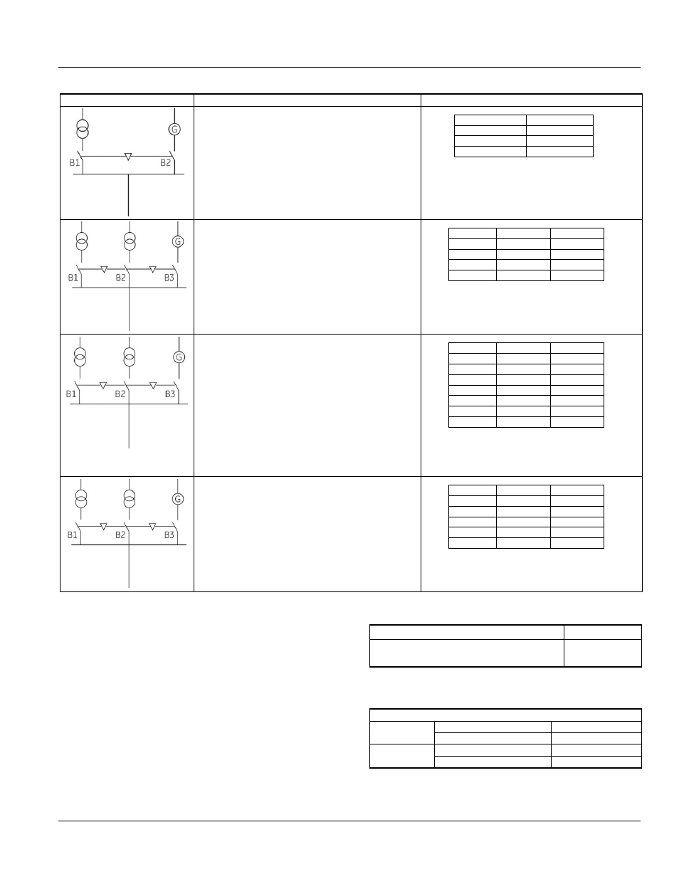
Table 6.15. Interlock Configurations
Typical Circuit
Interlock Configuration
Possible Combinations
Type A
1 from 2 way interlock
2 cable configuration
Interlocking between two circuit breakers
One normal power supply
One generator (emergency) supply
B1
B2
O
O
1
O
O
1
B1 can close only if B2 is open.
B2 can close only if B1 is open.
Type B
1 from 3 way interlock
6 cable configuration
Interlocking among three circuit breakers
Three power supplies (generator or transformers)
feeding the same busbar but parallel operation is
prevented.
Available on request.
B1
B2
B3
O
O
O
1
O
O
O
1
O
O
O
1
Only 1 of 3 breakers can be closed.
Type C
1 from 3 way interlock
6 cable configuration
Interlocking among three circuit breakers
Two bus sections can be powered by single
transformer (bus coupler closed) or both
transformers (bus coupler open).
Available on request.
B1
B2
B3
O
O
O
1
O
O
O
O
1
O
1
O
1
1
O
O
1
1
v
O
1
Any two from three breakers can be closed.
Any one from three breakers can be closed.
Two breakers must be closed to prevent the
third breaker from closing.
Type D
1 from 3 way interlock
6 cable configuration
Interlocking between three circuit breakers
Two normal power supplies not set in parallel.
One power supply may assist the priority circuit.
Available on request.
B1
B2
B3
O
O
O
1
O
O
O
O
1
1
O
1
O
1
O
B1 and/or B3 can be closed only if B2 is open.
B2 can only be closed if B1 and B2 are both
open.
Contact factory for availability
Bell Alarm with Lockout
The bell alarm provides remote indication that the circuit
breaker has opened because of an electrical fault. The
Lockout feature is integral to the trip unit. When a Bell
Alarm is supplied with the breaker, the trip unit dial is set
and locked to the manual position. In order to re-close
the breaker, the Lockout button must be pushed in/reset
on the trip unit 1-Form C contact (Tables 6.16 and 6.17).
Table 6.16. Bell Alarm Switches
Switch Configuration
Cat. No.
One single pole, double throw switch
(1-Form C contact)
GBAT1R
Table 6.17. Bell Alarm Ratings (Common NO/NC
Contact Configuration)
Ratings
AC
120 Vac
6 A
250 Vac
6 A
DC
125 Vac
0.5 A
250 Vac
0.25 A