GE Industrial Solutions EntelliGuard G User Manual
Page 25
DEH-41304C
EntelliGuard® G Circuit Breaker
13 March 14
Section 5 – Locks and Interlocks
©2012 General Electric All Rights Reserved
25
Figure 5.12. Right-Hand Hinged Board Door Bracket
Location Detail
5. Ensure the circuit breaker is in the DISCONNECTED
POSITION.
6. Close the panel door. Ensure the interlock lever is in the
lifted position.
7. Close the door and rack-in the circuit breaker in the
cassette. Follow steps 7 thru 12 in the section “Drawout
Circuit Breaker Operation“ already illustrated for
racking the circuit breaker in the cassette.
8. After reaching CONNECTED position, test the now
locked panel door to ensure it does not open.
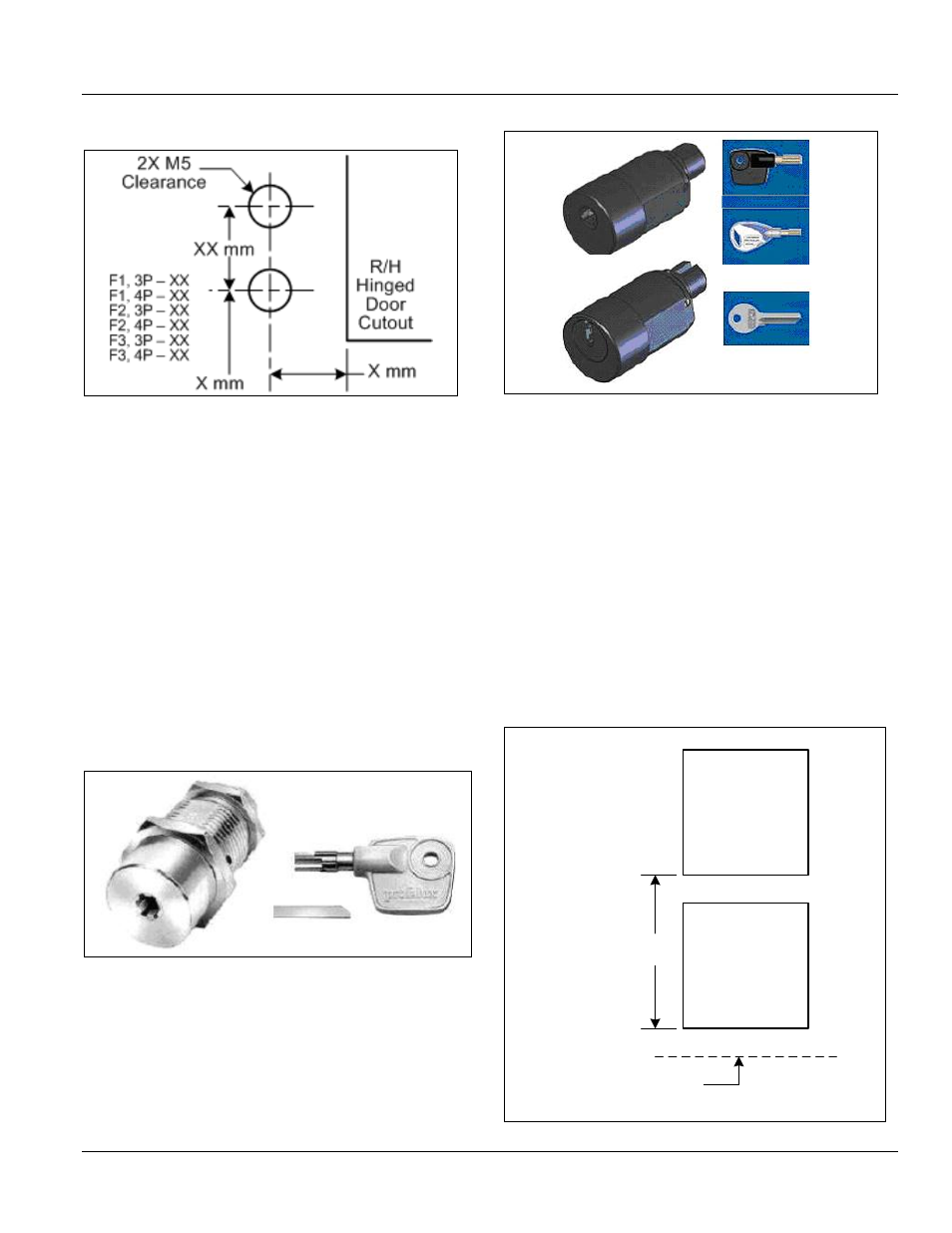
KEY LOCKS AND INSTALLATION
Two types of key locks fit on the cassette (Figs. 5.13 and
5.14).
Profalux
Ronis
Figure 5.13. Profalux Key Interlock
Figure 5.14. Ronis Key Interlock
TWO-BREAKER CABLE INTERLOCK INSTALLATION
Figs. 5.15 and 5.16 provide information needed to calculate
the correct cable length. More information on three-breaker
and other combinations of cable interlocks is available on
request.
Vertical Mounting (Fig. 5.15)
1. Cassette pitch “A” is from the bottom face of one
cassette to the bottom face of the other. Dimension
“A” must be no less than 60 cm.
2. Ensure that the minimum cable radius is not less than
125 mm. Minimum cable length is “A” + 100 cm.
Longer cables may be used; however, they must be
free from obstruction and no longer than 3 m.
Figure 5.15. Vertical Mounting Dimensions
Top
Circuit
Breaker
Bottom
Circuit
Breaker
“A” cm
10 cm (Min.) Cable