GE Industrial Solutions EntelliGuard G User Manual
Page 36
EntelliGuard® G Circuit Breaker
DEH-41304C
Section 7 – Accessories Installation
13 March 14
36
©2012 General Electric All Rights Reserved
1. Remove the circuit breaker from its cassette.
2. Rotate the shutter operating lever to open the shutter
(Fig. 7.7).
3. Release the shutter operating lever to close the
shutters.
Figure 7.7. Shutter Operating Lever Location
A Shutter Operating Lever
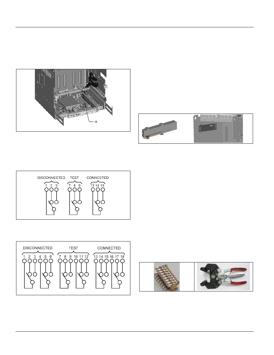
CARRIAGE POSITION SWITCH INSTALLATION
Two configurations are available:
One device for each position (Fig. 7.8).
Figure 7.8. One Switch Configuration (GCPS1R)
Two devices for each position (Fig. 7.9).
Figure 7.9. Two Switch Configuration (GCPS2R)
Each switch has a 1.5 m long wire for each switch
terminal. Each wire is identified with a ferrule.
The device will indicate DISCONNECTED even when the
circuit breaker is fully withdrawn or removed.
Mounted on the left-hand side of the cassette for all
frames.
Mounted on right hand side when used with the
optional side mounted secondary disconnect for frame
1 ANSI/UL circuit breaker. No fasteners are required. To
insert, feed the wires through the large opening on the
side of the cassette. Seat the carriage position switch in
the front side of the hole first. Then use this as a pivot
and ensure that all four tabs lock in place (Fig. 7.10).
Figure 7.10. Carriage Position Switch Location
BUSBAR/CABLE GROUNDING (OPTIONAL)
This feature is used for grounding the circuit breaker
terminals on the busbar or the cable side. The pack
contains:
Isolating contact (cluster) pliers for removal of the main
isolating contacts.
Grounding bar with spring-pressured ground contact.
The bar is reversible to fit top or bottom terminal sets.
Necessary mounting M10 bolts and washers.
Anti-trip plate.
CLUSTERS
Clusters are the main isolating contacts which are installed
on the rear terminals on the moving portion of the
withdrawable unit. Cluster contacts may be easily and
quickly removed and replaced using cluster pliers (Figs. 7.11
and 7.12).
Figure 7.11. Clusters
Figure 7.12. Cluster Pliers
Cluster tool
Cluster
Cluster tool
Cluster
Clusters are mounted horizontally and vertically through
cluster pads for different frame sizes. The slot is provided on
the terminals for locking the clusters. For higher current and
short circuit ratings the clusters are assembled in parallel
(Fig. 7.13).