GE Industrial Solutions EntelliGuard G User Manual
Page 32
EntelliGuard® G Circuit Breaker
DEH-41304C
Section 6 – Accessories Description
13 March 14
32
©2012 General Electric All Rights Reserved
Charging Spring Status Indicator
Factory-installed on the motor, this auxiliary switch
indicates that the circuit breaker is charged and is
standard with the spring-charging motor (Table 6.18).
Table 6.18. Spring Charged Contact (1 NO)
Ratings
Cat. No.
AC
120 Vac
6 A
GSCC1R
250 Vac
6 A
DC
125 Vac
0.5 A
250 Vac
0.25 A
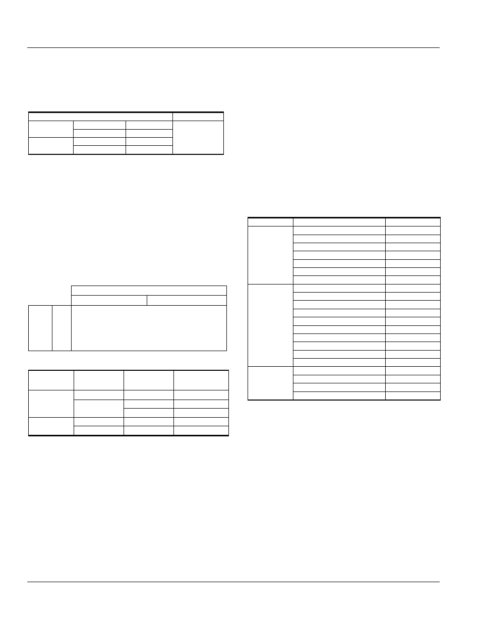
Secondary Disconnects (Factory-installed/Field
Installable)
Inputs and outputs to the circuit breaker are wired
through secondary disconnects located on either the top
or the side (Envelope 1 only) of the breaker. The plug-style
secondary disconnects engage mating disconnects in the
breaker cubicle when the breaker is in the TEST or
CONNECT position. Up to 78 points are available so that
all breaker accessories can be wired to dedicated
disconnect points. See Table 6.19 for block location and
Table 6.20 for secondary disconnect parts.
Table. 6.19. Block Location
Top Disconnect
Block B
Block A
Si
de
D
is
con
nect
Bl
ock
A
circuit breaker/cradle
viewed from the front
Table. 6.20. Secondary Disconnect Parts
Breaker
Type
Mounting
Number of
Poles
Cat. No.
Fixed
top
39 pole set
GSDFTR1
side
top
78 pole set
GSDFTR2
78 pole set
GSDFSR
Drawout
side
78 pole set
GSDWTR
39 pole set
GSDWSR
Set contains both the male and female sides of the secondary
disconnect.
Drawout kits include the metal bracket for connections to the
cassette.
Breakers ordered with side mounted disconnects come standard
with 78 pole secondary disconnect.
Ground Fault
The EntelliGuard TU Trip Unit provides a non-core CT
input for zero sequence or residual summation current.
The expected ratio is 1A = 100%.
Neutral Rogowski CT’s
The Neutral Rogoswki CT’s are used to measure the
Neutral Current and is required when Internal Ground
Fault is selected on the trip unit. There are two types
available:
1. Encased with Terminal Screws: The Rogowski coil
is encased in a plastic mold with two terminal
screws. No additional mounting hardware is
required as the encasing is molded to the
mounting dimensions. Table 6.21
2. Loose Rogowski Coil with separate mounting
hardware: The coil and mounting hardware are
separate. The coil comes with the two wire leads
for connection to a terminal block. Table 6.21a
Table 6.21. Neutral Rogowski CTs
(Encased with Terminal Screws)
Envelope
Current Rating
Cat. No.
1
400 A
G04HNRCE
600/630 A
G07HNRCE
800 A
G08HNRCE
1000 A
G10HNRCE
1200/1250 A
G13HNRCE
1600 A
G16HNRCE
2000 A
G20HNRCE
2
400 A
G04MNRCE
600/630 A
G07MNRCE
800 A
G08MNRCE
1000
G10MNRCE
1200/1250 A
G13MNRCE
1600 A
G16MNRCE
2000 A
G20MNRCE
2500 A
G25MNRCE
3000/3200 A
G32HNRCE
4000 A
G40HNRCE
3
3000/3200 A (1600 A x 2)
G32GNRCE
4000 A (2000 A x 2)
G40MNRCE
5000 A (2000 A x 2)
G50MNRCE
6000/6400 A (3200 A x 2)
G04MNRCE