7 network interlock – GE Industrial Solutions EntelliGuard 800–2000 A Frames, 240–600 Vac Maintenance Manual User Manual
Page 58
EntelliGuard™ 800–2000 A Power Circuit Breakers
Chapter 8. Accessory Maintenance
48
8.7 Network Interlock
The Network Interlock provides a means of locking out a
breaker to coordinate its operation with other breakers in
the distribution network. When activated by the
EntelliGuard Messenger, the Network Interlock prevents
the breaker from closing. When the EntelliGuard
Messenger issues a RESET signal, the breaker can be
closed either remotely or locally. The Network Interlock
accessory includes a manual reset lever to reset the device
in the absence of a signal from the EntelliGuard
Messenger.
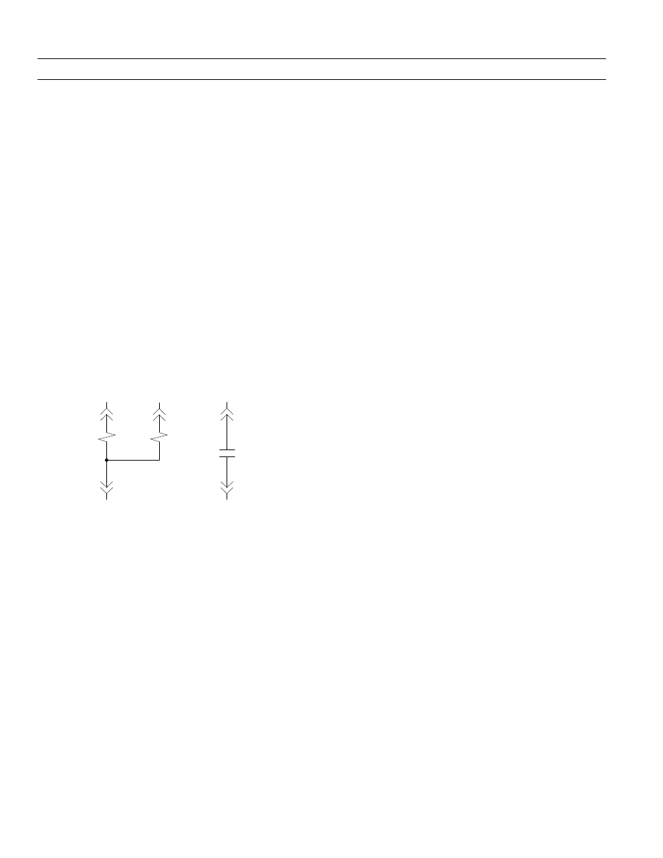
The Network Interlock consists of a trip coil, a reset coil,
and a status switch. The device connections to the
secondary disconnect are shown in Figure 62. When
voltage is applied across the trip coil, the device locks out
the breaker. Conversely, when voltage is applied to the
reset coil or when the reset lever is depressed, the Network
Interlock resets, allowing the breaker to close. The
Network Interlock does not close the breaker itself.
Renewal parts for the Network Interlock are available as a
complete kit or as a module only. The Network Interlock
accessory is only available on electrically operated
breakers.
Figure 62. Network Interlock connections to the secondary disconnect.
Removing the Network Interlock Module
Use the following procedure to remove the Network
Interlock.
1. Disconnect the six wires from the Network Interlock
device. Label each wire as it is removed. Cut wire ties
as necessary.
2. Remove the manual reset assembly by removing the
two hex-head screws as shown in Figure 65.
3. Remove the accessory mounting plate as shown in
Figure 63.
4. Remove the Network Interlock module from the
mounting plate by removing the three sets of nuts
and washers, as shown in Figure 64.
Installing the Network Interlock Module
Use the following procedure to install the Network
Interlock module as a replacement.
1. Open the circuit breaker and remove it from the
cubicle or substructure. Check to ensure the breaker
closing springs are DISCHARGED.
2. Carefully place the circuit breaker on a suitable
working surface, resting on the primary disconnects,
so that the bottom of the circuit breaker is accessible.
3. Fasten the Network Interlock module to the accessory
mounting plate using three sets of # 8-32 nuts, spring
washers, and flat washers as shown in Figure 64.
4. Fasten the Shunt Trip accessory to the mounting plate
beside the Network Interlock. See Section 8.2 or DEH-
168 for detailed instructions.
5. Assemble the accessory mounting plate to the circuit
breaker frame using four sets of # 10-32 screws, spring
washers, and flat washers as shown in Figure 63
6. Ensure the Network Interlock is in the RESET state
(shown in Figure 66) by manually rotating the reset
lever counterclockwise. If the Network Interlock was
SET, this operation will cause the set lever to retract
(counterclockwise) away from the trip paddle.
7. With the breaker open, charge the breaker closing
springs. Do not close the breaker. Adjust the gap
between the Network Interlock set lever and trip
paddle by rotating the socket-head adjusting screw as
shown in Figure 66. The distance between the set lever
and the trip paddle must be between 0.060 and 0.090
inch.
8. Connect the six wires to their corresponding terminals
on the Network Interlock device.
9. Reset the Network Interlock by pushing the manual
reset button. The Network Interlock status circuit
should be open. Close the breaker manually or
electrically. The breaker should close properly.
10. Set the Network Interlock by applying 120 VAC across
terminals 15 and 21 on the secondary disconnect. The
breaker should trip open and the status circuit should
change from open to close.
11. Charge the breaker manually or electrically. Close the
breaker. The breaker should trip open, discharging
the closing springs.
12. Reset the Network Interlock by applying 120 VAC
across terminals 20 and 21 on the secondary
disconnect. The status circuit should change from
closed to open.
13. Charge and close the breaker. The breaker should
close properly.
14. Set the Network Interlock, and repeat Steps 9 through
13.
15
NI Set
Coil
20
21
NI Reset
Coil
1
3
2
16
19
4
5
NI Status
Contact