3 charging motor – GE Industrial Solutions EntelliGuard 800–2000 A Frames, 240–600 Vac Maintenance Manual User Manual
Page 51
EntelliGuard™ 800–2000 A Power Circuit Breakers
Chapter 8. Accessory Maintenance
41
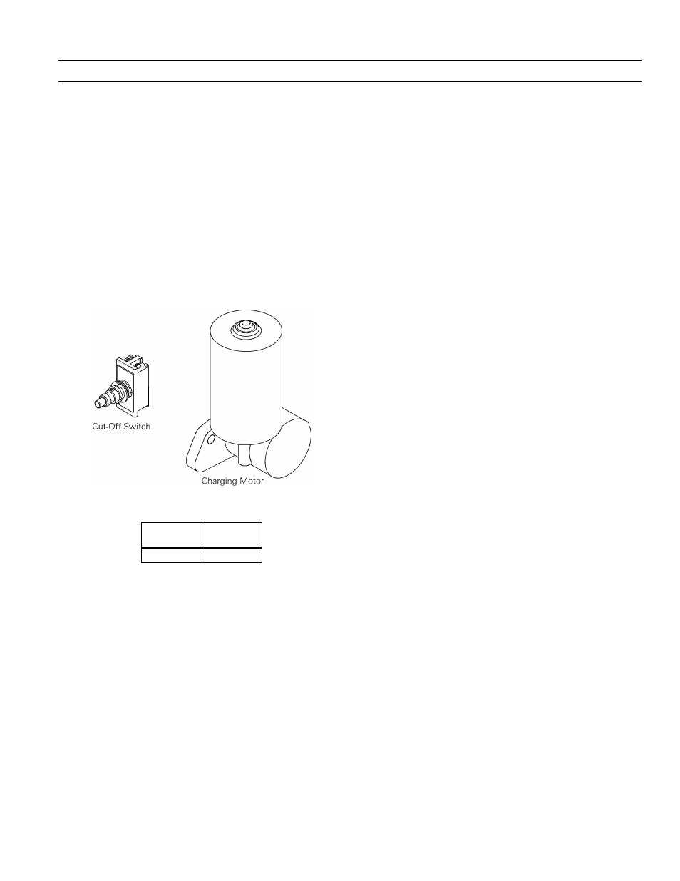
8.3 Charging Motor
The Charging Motor provides a means of electrically
charging the springs that close the breaker. The Charging
Motor is available only as a factory-installed option. It is
always provided on electrically operated breakers.
The circuit breaker closing springs are charged automati-
cally when control voltage is applied to terminals 8 and 17
of the secondary disconnects. When the springs are fully
charged, a cutoff switch automatically de-energizes the
motor. The closing springs will recharge automatically
after the breaker closes.
Renewal parts for the Charging Motor are the motor and
the cut-off switch, illustrated in Figure 51. The catalog
number and electrical characteristics of the Charging
Motor are listed in Table 8.
Figure 51. Charging Motor and cut-off switch.
Catalog
Number
Voltage
Range, Vac
568B596G5 104–127
Table 8. Catalog number and operating voltage for the Charging Motor
accessory.
Removing the Charging Motor
Use the following procedure to remove the Charging
Motor for replacement, as illustrated in Figure 52.
1. Carefully place the breaker on a suitable working
surface, so that the right front of the breaker is
accessible.
2. Disconnect the motor wires at the connector.
3. Remove the three bolts and lock washers securing
the motor to the breaker mechanism.
4. Remove the motor and the three mounting spacers.
Installing the Charging Motor
Use the following procedure to install a replacement
Charging Motor, as illustrated in Figure 52.
1. Place the motor in position with the three mounting
spacers on the breaker mechanism and insert the
three mounting bolts and lock washers. Tighten the
bolts to 110 in-lb.
2. Connect the motor wires by plugging the connector
into place.
Removing the Motor Cut-Off Switch
Use the following procedure to remove the motor cut-off
switch, as illustrated in Figure 52.
1. Carefully place the breaker on a suitable working
surface, so that the right front of the breaker is
accessible.
2. Remove the breaker escutcheon, as described in
Section 7.5.
3. Disconnect the wires at the screw terminals on the
switch.
4. Remove the nut from the switch stem under the
hole in the mounting bracket.
5. Remove the cut-off switch.
Installing the Motor Cut-Off Switch
Use the following procedure to install the replacement
motor cut-off switch, as illustrated in Figure 52.
1. Screw one of the locking nuts onto the switch barrel
and place the flat washer over the nut.
2. Place the cut-off switch in position with the switch
stem through the hole in the mounting bracket.
Attach the mounting nut and secure the switch.
3. Connect the wires at the screw terminals on the
switch.