2 secondary disconnect – GE Industrial Solutions EntelliGuard 800–2000 A Frames, 240–600 Vac Maintenance Manual User Manual
Page 41
EntelliGuard™ 800–2000 A Power Circuit Breakers
Chapter 7. Maintenance of Standard Parts and Assemblies
31
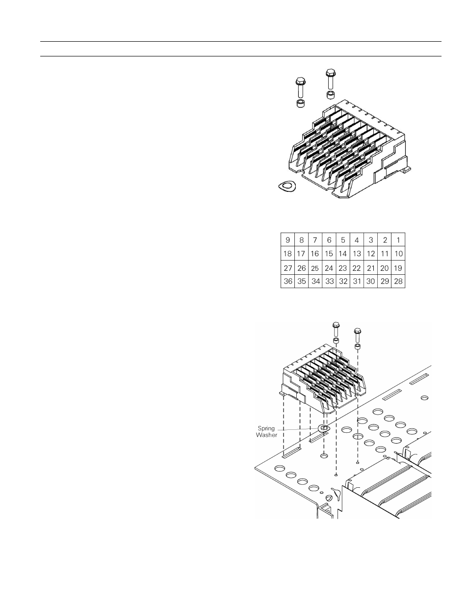
7.2 Secondary Disconnect
The secondary disconnect, illustrated in Figure 30, pro-
vides connections between the breaker control circuits and
external circuit elements. It is attached to a mounting
plate on the breaker back frame. It automatically makes or
breaks the control circuit connections as the breaker is
racked in or out of its compartment. Figure 31 illustrates
the numbering of the terminals in the secondary
disconnect.
Secondary Disconnect Removal
To remove a secondary disconnect, use the following pro-
cedure, as illustrated in Figure 32.
1. Unplug all control circuit wires from the secondary
disconnect, carefully marking each wire with its
position number in the disconnect.
2. Remove the two screws and standoffs securing the
disconnect to the mounting plate.
3. Slide the disconnect mounting feet out of the slots
in the mounting plate. Remove the spring washer if
it has detached from the molded pin on the under-
side of the disconnect.
Secondary Disconnect Installation
To replace a secondary disconnect, use the following
procedure, as illustrated in Figure 32.
1. Place the spring washer on the molded pin on the
underside of the disconnect body and hold it in
place.
2. Slide the mounting feet on the disconnect into the
two slots in the secondary disconnect mounting
plate.
3. Place the two screws and standoffs into the slots on
the front of the disconnect and into the tapped
holes in the mounting plate. Tighten to 40 in-lb.
4. Insert the control circuit wires into the correct posi-
tions in the secondary disconnect.
Figure 30. Secondary disconnect.
Figure 31. Secondary disconnect terminal numbering. (As seen from
the front of the breaker.)
Figure 32. Removing or installing the secondary disconnect.