5 adjusting the contacts – GE Industrial Solutions EntelliGuard 800–2000 A Frames, 240–600 Vac Maintenance Manual User Manual
Page 36
EntelliGuard™ 800–2000 A Power Circuit Breakers
Chapter 6. Contact Maintenance
26
6.5 Adjusting the Contacts
Adjust the contact depression whenever contacts are
replaced. In addition, check and adjust, as necessary, at
the normal maintenance interval.
Contact Adjustment on EGS08, EGF08, and
EGH08 Breakers
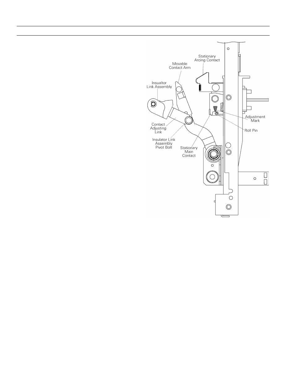
The following procedure is illustrated in Figure 23.
1. Contact depression is correct if the center of the roll
pin falls within the two sides of the scribed adjust-
ment mark on the side of the stationary main con-
tact.
2. If adjustment is necessary, remove the nut, washer,
and bushing from the end of the pivot bolt securing
the insulator link assembly to the movable contact
arm, then remove the bolt and other washer and
bushing.
3. Turn the contact adjusting link in or out of the insu-
lator link assembly. Increase its length to increase
contact depression and shorten the link to decrease
contact depression.
4. Reassemble the insulator link assembly to the con-
tact arm with the pivot bolt, nut, two washers, and
two bushings.
Contact Adjustment on EGX08, EGS16,
EGF16, EGH16, EGS20, and EGF20 Breakers
The following procedure is illustrated in Figure 24.
1. Remove the arc chutes and phase barriers, as
described in Section 6.2.
2. To establish a reference for measurement, fasten
the aluminum arc chute retainer to the breaker
mechanism frame with small C clamps, as shown.
Ensure that the C clamps do not interfere with any
moving parts.
3. Measure dimension ‘A’ with the contacts open and
again with the contacts closed. Note that the meas-
urement is made from the second contact spring
end (first stationary main contact). The difference
in the measurements should be 0.06–0.10 inch,
which provides 0.05–0.08 inch main contact depres-
sion.
4. To adjust contact depression, do the following:
a. Remove the retaining ring from one side of the
pin connecting the drive link to the movable con-
tact arms and remove the pin.
b. Adjust the depression by turning the link in one-
half-turn increments. Note that the link has left-
hand threads. One-half turn changes dimension
A by about 0.03 inch, which is equivalent to about
0.02 inch in contact depression.
5. Repeat for all poles.
Figure 23. Contact adjustment on EGS08, EGF08, and EGH08 breakers.