3 flux shifter – GE Industrial Solutions EntelliGuard 800–2000 A Frames, 240–600 Vac Maintenance Manual User Manual
Page 42
EntelliGuard™ 800–2000 A Power Circuit Breakers
Chapter 7. Maintenance of Standard Parts and Assemblies
32
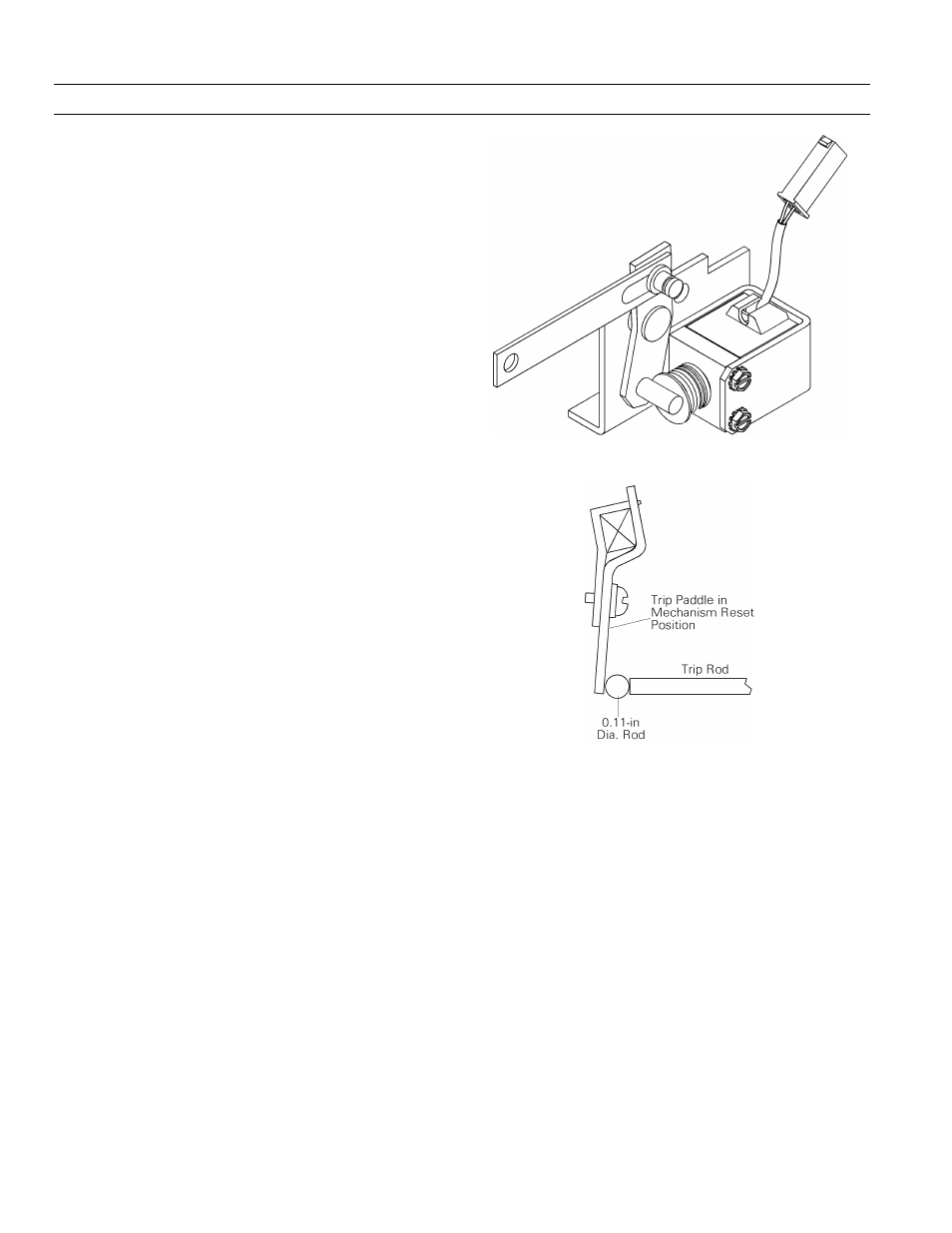
7.3 Flux Shifter
The function of the flux shifter, illustrated in Figure 33, is
to actuate the trip shaft and trip the breaker upon receiv-
ing a signal from the EntelliGuard Messenger™.
Flux Shifter Adjustment
The only adjustment required to the flux shifter mecha-
nism is the trip rod length. As shown in Figure 34, the
clearance between the trip rod end and the trip paddle is
set to 0.11 ± 0.03 inch. To make this adjustment, open the
breaker and charge the closing springs to restore the
mechanism to the Reset position. Loosen the lock nut on
the trip rod, rotate the adjuster until the proper gap is
attained, then retighten the lock nut.
Removing the Flux Shifter
The following procedure is illustrated in Figure 35.
1. Remove the snap ring connecting the reset arm to
the main shaft and slide the arm off its mounting
point.
2. Unplug the connector at the end of the flux shifter
leads.
3. Remove the two mounting bolts and lock washers
from underneath the breaker base, then lift off the
flux shifter.
Installing the Flux Shifter
The following procedure is illustrated in Figure 35.
1. Put the replacement flux shifter into position, lining
up the solenoid plunger with the end of the trip rod
and the operations counter link (if present) with
the end of the reset arm. Insert the two bolts and
lock washers from beneath the bottom plate of the
breaker and tighten to 32 in-lb.
2. Slide the end of the reset arm onto the connection
on the breaker main shaft and secure with the snap
ring.
3. Connect the leads to the secondary disconnect.
Figure 33. Flux shifter.
Figure 34. Flux shifter adjustment.