GE Industrial Solutions EntelliGuard 800–2000 A Frames, 240–600 Vac Maintenance Manual User Manual
Page 56
EntelliGuard™ 800–2000 A Power Circuit Breakers
Chapter 8. Accessory Maintenance
46
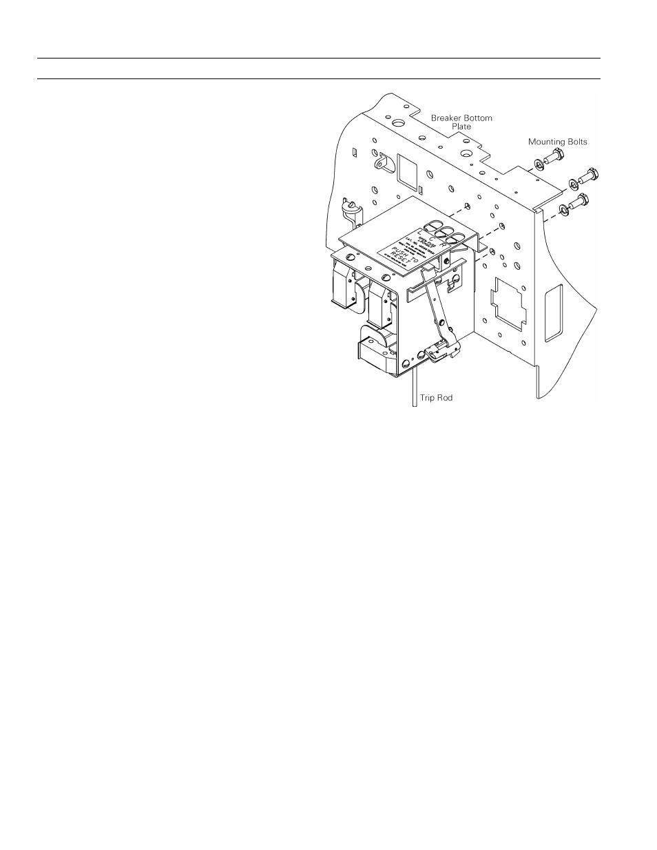
2. Remove the three mounting bolts and lock washers
securing the Open-Fuse Lockout to the bottom plate
of the breaker.
3. Remove the Open-Fuse Lockout straight out from
the front of the breaker.
Installing the Open-Fuse Lockout, 2000 A
Breakers
Use the following procedure, illustrated in Figure 58, to
install a replacement Open-Fuse Lockout.
1. Place the replacement Open-Fuse Lockout in
position, carefully guiding the trip rod through the
hole in the trip rod guide.
2. Insert the three bolts and lock washers from the top
of the breaker bottom plate into the tapped holes in
the Open-Fuse Lockout mounting bracket. Tighten
to 96 in-lb.
3. Connect the wires from the coils on the Open-Fuse
Lockout to the secondary disconnect block as fol-
lows:
• Phase A to terminals 22 and 23.
• Phase B to terminals 24 and 25.
• Phase C to terminals 26 and 27.
4. Adjust the Open-Fuse Lockout as follows:
a. Charge the closing springs with the manual
charging handle and close the breaker.
b. The dimension between the end of the trip rod
and the trip paddle should be 0.10–0.14 inch. If
necessary, loosen the trip rod lock nut and run
the rod in or out to attain the proper clearance.
c. With the Open-Fuse Lockout energized, the
breaker must
TRIP
and the
RESET
button must
move forward to the front plate. In this condition,
the breaker must be held trip free.
Figure 58. Open-fuse lockout installation and removal.