Front of vehicle, Caution – Draw-Tite 30035 FIFTH WHEEL RAILS User Manual
Page 21
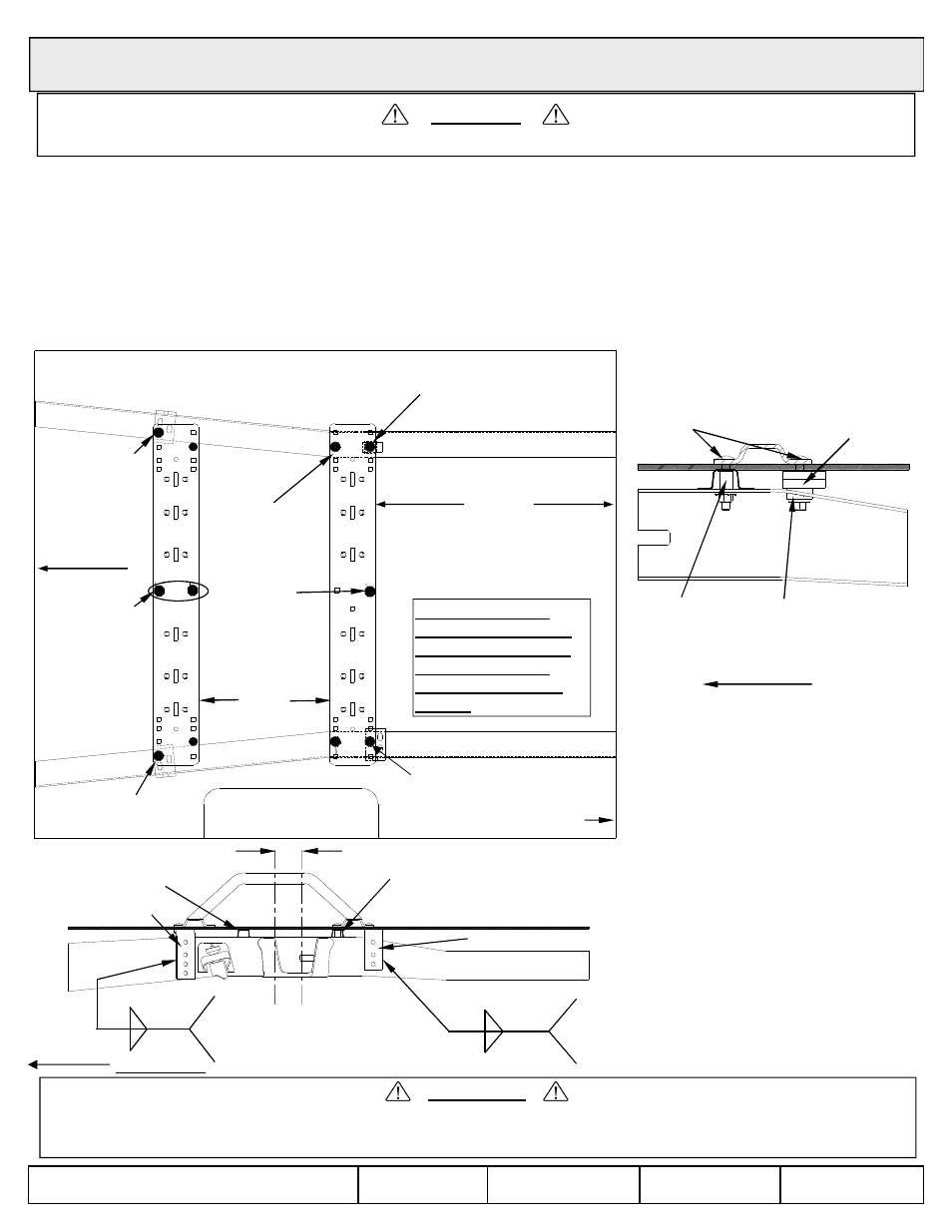
3” Carriage bolt, 1/2” spacers &
bevel washers
Drill through top of frame
See Detail Inside Frame
2007 And Newer Toyota Tundra 6.5’ & 8’ Beds – requires Service Kit 58309
(Crewmax 5.5’ Bed requires Reese Sidewinder
TM
Pinbox)
CAUTION!
Read pages 2-3 of these instructions before starting installation. Failure to do so could result in significant vehicle damage!
IMPORTANT NOTES FOR THIS INSTALLATION:
1. Use the 58309 service kit together with the 30035 mounting kit. Read p. 1-3 of the 30035 instruction for general
information.
2. The mounting holes for Row 3 go through the inside of the bed sill. After measuring, drill an 1/8” hole for the rear rail.
Be sure the hole is in the center of the bed sill. Make sure it lines up correctly. Drill a 9/16” hole through the bed and
the top of the frame on both sides. For the Row 4 passenger side attachment, drill through the bed and the top of
the frame as well.
3. The rear rail on the passenger side is secured directly to the frame with 3” carriage bolts provided in the 58309 kit.
For the Row 3 attachment, a tube spacer should be placed inside the bed sill on top of the frame and under the
bottom of the bed. Line up the spacer with the drilled hole before inserting the carriage bolt. Repeat for both sides.
See Detail Inside Frame.
Rear Passenger Side
Detail Inside Frame
3” Carriage Bolts
Tube spacer
bevel washer on bottom
1/2” spacers (2),
bevel washer
29 3/4”
5.5’, 6.5’, 8’ Bed
Measure from rear edge of
truck bed to rear edge of
base rail.
Front of
Vehicle
R
O
W
1
R
O
W
2
R
O
W
3
R
O
W
4
3” Carriage bolt &
tube spacer
Drill through top of
frame (both sides)
Use rear
center hole
only in rear
1-3/4” carriage
bolt with long
bracket
Do not install on a
NOTE:
z 2006,2007,2008,2009,2010,2011,2012,2013 Cequent Performance Products, Inc.
Made in China
30035IN
9/4/13
Rev. R
CAUTION!
Check for obstructions before drilling. Failure to do so could result in damaged fuel or brake lines, structural members, etc. CEQUENT
PERFORMANCE PRODUCTS, INC. does its best to communicate tow vehicle manufacturer changes; however, it is ultimately the
responsibility of the installer to prevent damage due to installation.
Short bracket
Bed Sill
*
Optional weld
pattern
*
1/4 2
1/4 2
Axle Center
King pin center approx. 3-1/2”
forward of axle center
Long bracket
Tube spacer
inside bed sill
*
1/4 1.5-3
1/4 2
4. For the Row 4 passenger side
attachment, stack two 1/2”
spacers and a bevel washer,
provided in the 58309 kit, to fill
the gap between the bed and the
frame. Use another bevel washer,
conical toothed washer, and hex
nut to fasten the 3” carriage bolt
in place. See above drawing.
5. Install the long brackets on the
front rail and the short bracket on
the rear rail driver side using the
1-3/4” carriage bolts provided in
the 58309 kit. All other
attachments to the bed use 2”
carriage bolts from the 30035 kit.
FRONT OF
VEHICLE
Tube spacer
inside bed sill
bevel washer on bottom
Rear Edge of
Truck Bed
only in rear
base rail
1-3/4” carriage bolt with
short bracket
1-3/4” carriage
bolt with long
bracket
Do not install on a
truck with a 5’7” long
bed unless the trailer
is equipped with a
Reese Sidewinder
TM
Pinbox.
SHEET 20 0F 21
NOTE:
Must install center
bolt in one of the
center holes in
each rail.
Check to make
sure center bolt
does not interfere
with bed sill.
Front
of
Vehicle
Drivers Side
Use 5
th
wheel legs to
locate front
rail.