Draw-Tite 65060 FRONT MOUNT RECEIVER User Manual
Front mounted receiver installation instructions, Dodge 3500, Part numbers
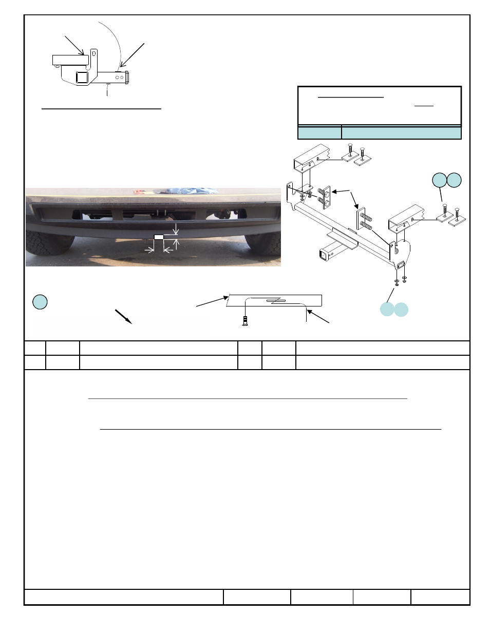
Front Mounted Receiver
Installation Instructions
Dodge 3500
Part Numbers:
65060
Hitch Shown In Proper Position
Equipment Required: Bolt leader (Provided)
Wrenches: 18MM DEEP WELL, 7/8”
Drill Bits: 1/2”
Other Tools: Tape, Cutting tool for hard
Plastic fascia. File for enlarging hole.
Tighten all M12 fasteners with torque wrench to 92 Lb.-Ft. (124.7 N.M.)
z
2012 Cequent Performance Products
Sheet 1 of
65060N
8-20-12
Rev. A
j
Qty. (4)
Carriage Bolt, 1/2” -13 x 2” Gr5
k
Qty. (4)
Block 1/4” x 1-1/2” x 2
l
Qty. (4)
1/2” Helical lock washers
m
Qty. (4)
Hex Nut, 1/2”
Tighten all 1/2” fasteners with torque wrench to 75 Lb.-Ft. (101.7 N.M.)
Note: check hitch frequently, making sure all fasteners and ball are properly tightened. If hitch is removed, plug all holes in trunk pan or other body panels to
prevent entry of water and exhaust fumes. A hitch or ball which has been damaged should be removed and replaced. Observe safety precautions when working
beneath a vehicle and wear eye protection. Do not cut access or attachment holes with a torch.
This product complies with safety specifications and requirements for connecting devices and towing systems of the state of New York, V.E.S.C. Regulation V-5
and SAE J684.
Fastener Kit: 65060F
Form: F205 Rev A 5-6-05
9,000lb.
MAXIMUM WINCH LINE PULL
CARGO CAPACITY – Do not exceed
500 LB (227 Kg.) or Truck Front
Gross Axle Weight Rating, (GAWR).
1.
It is necessary to trim a section out of the plastic fascia attached to bottom of bumper. See Picture
above.
2.
Locate and remove the18mm flange nuts on outside of truck frame rails, slide the bolt plate back into
frame but do not remove.
CAUTION: DO NOT completely remove bolt plate, if removed bumper will drop and may result in injury.
3.
Raise hitch into position, slide bolts plates back thru frame and into hitch side brackets. Loosely install
nuts removed in Step 2.
4.
With front Bolts installed use rear holes as a guide to drill (4) 1/2” holes into frame.
5.
Use 1/2” bolt leaders to pull 1/2” carriage bolts and spacer blocks thru hole (if hole is not available you
must enlarge existing hole or drill one for the hardware) in the frame and through the hitch as shown
(FIG.2). Square shoulders of bolts must be pulled into blocks to engage with the sides of frame. Check
to see that carriage bolt is engaged in block holes. Install helical lock washers and hex nuts as shown.
6. Tighten flange nuts and torque all hardware to the specs specified below.
CONSULT VEHICLE OWNER BEFORE TRIMMING OR CUTTING PLASTIC AIR DAM.
This is a magnified
view of a Bolt Leader
5
1
2
3
4
TRIM FASCIA AS SHOWN
FRAME
FASCIA
FIG.1
FIG.2
Frame rail
Bolt
leader
Bolt
Plate
3 ½”
1”