De en fr it es – OSRAM EASY DMX 16x4 SO User Manual
Page 31
DE
EN
FR
IT
ES
31
EASY DMX SO
XII 2009
Installation
•
Terminate each chain on the link by placing a 120 Ω resistor across the “DMX +”
and “DMX –” conductors of the last DMX device on the chain. Alternatively, activate
the internal termination resistor at the last DMX device if this feature is supported.
•
Long parallel runs of AC power and control data cables may cause interference
on the DMX link and must be avoided. Even if not required by law, use separate
conduits for power and data cables.
Connecting the control unit
The procedure for connecting the control unit is different for “single light point” and
“multiple light points” applications; see “Defining light points”.
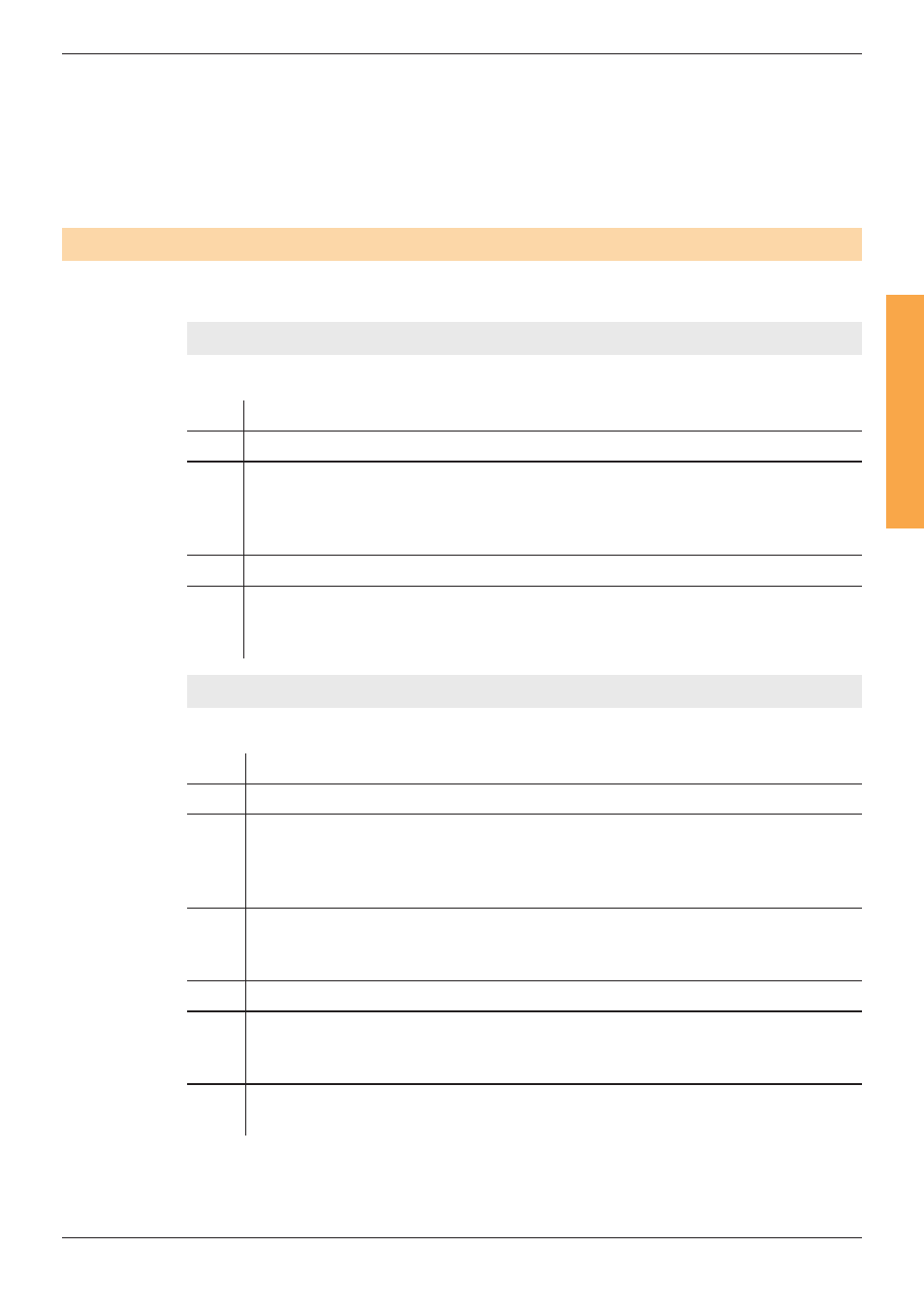
“Single light point” application
Proceed as follows:
Step Action
1
Connect EASY DMX output to DMX devices.
2
If necessary, set the DMX starting address of each DMX device to DMX
address 1.
See “Setting DMX addresses” and the separate instruction sheets of the
DMX devices.
3
Connect EASY devices and interfaces to EASY DMX input.
4
If necessary, change the default DMX channel configuration of EASY DMX
with the EASY Color Control software.
See “DMX channel configurations”.
“Multiple light points” application
Proceed as follows:
Step Action
1
Connect EASY DMX output to DMX devices.
2
Set the DMX starting addresses of the DMX devices according to the lighting
design requirements.
See “Setting DMX addresses” and the separate instruction sheets of the
DMX devices.
3
Activate the “Test mode” to run a preliminary test of the DMX addresses
setting.
See “Checking the DMX addresses setting”.
4
Connect EASY devices and interfaces to EASY DMX input.
5
If necessary, change the default DMX channel configuration of EASY DMX
with the EASY Color Control software.
See “DMX channel configurations”.
6
Arrange the mapping between light points and DMX addresses with the
EASY Color Control software.