OSRAM Touch DIM WCU User Manual
Touch dim wcu, Wall transmitter fitting instructions, Description
Page 1 of 2
Wall transmitter
Fitting instructions
TOUCH DIM WCU
Description
Purpose and application
The TOUCH DIM WCU wall transmitter, in combination with a
TOUCH DIM RC radio receiver, enables the wireless control
of two luminaire groups, each with up to 15
electronic control
gears featuring the TOUCH DIM
®
function.
The wall transmitter can be screwed or glued onto smooth
surfaces.
Function
The TOUCH DIM WCU wall transmitter sends radio signals to
the radio receiver, which converts these and transmits them to
the connected electronic control gears.
The wall transmitter does not require batteries and is absolutely
maintenance-free. The necessary transmission energy is
generated by an integrated inductive energy converter when the
pushbutton is pressed.
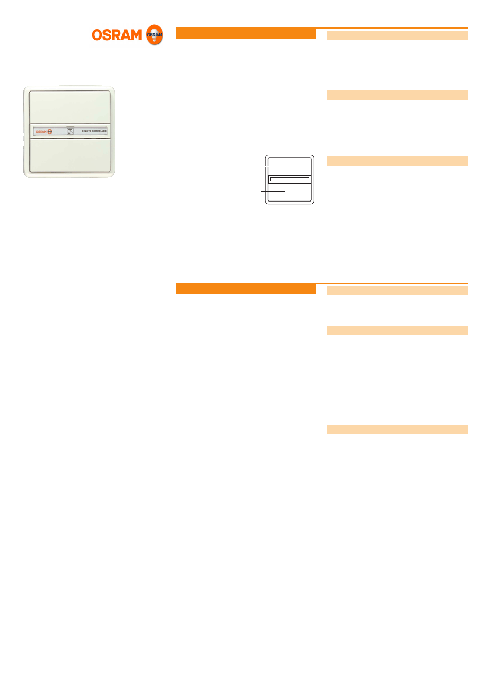
Design
The wall transmitter is made up of the following components:
• Pushbutton for luminaire group (A) connected to channel 1
(Ch 1) of the radio receiver
• Pushbutton for luminaire group (B) connected to channel 2
(Ch 2) of the radio receiver
Installation
Safety instruction
The wall transmitter must only be installed and put into opera-
tion by a qualified electrician. The applicable safety regulations
and accident prevention regulations must be observed.
Selecting the installation location
Observe the guide values for the radio transmission ranges
when selecting an installation location; see „Technical data“. If
necessary, perform a range test before installing the unit.
Do not mount the wall transmitter on metal or metal-coated
surfaces to avoid reducing the radio transmission range.
The radio transmission range between the wall transmitter and
radio receiver is influenced by the following factors:
• Construction materials
• Type and number of obstacles between the transmitter and
receiver
• Sources of interference and signal reflections
Attaching the wall transmitter
The wall transmitter can be attached using screws or, if the
surface is smooth such as glass, painted walls, tiles, furniture,
wood, etc., using the supplied adhesive pad.
Attaching with screws
Remove the central plate from the wall transmitter and use it
as a template to mark the drill holes.
Drill Ø 5 mm dowel holes.
Attach the central plate in such a way that the tabs that
are closer together are situated on the left and right of the
central plate.
Clip the frame and then the wall transmitter onto the central
plate.
Attaching with adhesive
Attach the adhesive film over the entire back of the assem-
bled wall transmitter.
Stick the wall transmitter onto a dry, dust-free and grease-
free surface.
A
B