OSRAM EASY DMX 16x4 SO User Manual
Page 28
28
XII 2009
EASY DMX SO
Description
Behaviour after a power failure
In the event of a power failure, the EASY DMX behaves as follows:
•
Lighting control mode: The last status prior to a power failure is automatically
restored.
•
Sequencer mode: The sequence restarts with the first active scene.
•
Daylight simulation: The simulation restarts with the first active scene.
Construction
The control unit is made up of the following components:
•
EASY signal input
• One 4-pin push-in contact (A) for connecting EASY devices with open wires, e.g.
EASY PB COUPLER:
1: Supply voltage
2: Sync signal
3: Infrared signal
4: Signal ground
• Two modular 4p4c plug-in contacts (B) for connecting EASY devices that provide
a built-in 4p4c plug, e.g. EASY IR
•
DIP switch (C) for activating termination resistor
•
DMX signal output
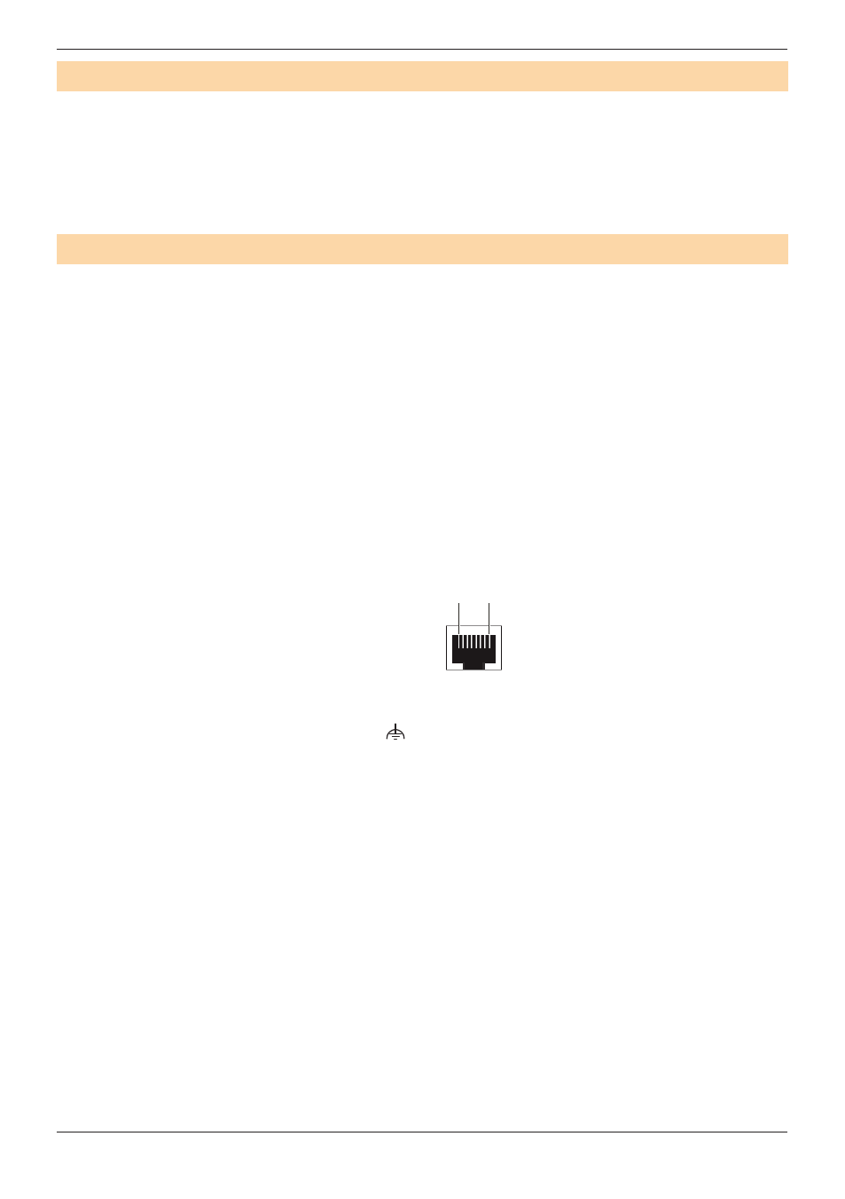
• RJ45 connector (D):
Pin 1: DMX –
Pin 2: DMX +
Pin 3: DMX shield
Pins 4-8: N.C.
1 8
• 3-pin push-in contact (E)
•
Mains connection (F): L, N,
•
DIP switches (G) for activating test mode (DIP switch 1) and master status (DIP
switch 2)
•
External switch input (H) for connecting light switches
•
LEDs (J)
•
EASY signal input (K): modular 4p4c plug-in contact (programming interface) for the
EASY PC KIT
•
Housing (L)