B&B Electronics ZXT9-MB2A-KIT - Manual User Manual
Page 53
Document Number: ZXTxRM-5110m
Page
53
1 – 0001b
2 – 0010b
3 – 0011b
4 – 0100b
5 – 0101b
6 – 0110b
7 – 0111b
8 – 1000b
9 – 1001b
10 – 1010b
11 – 1011b
12 – 1100b
13 – 1101b
14 – 1110b
15 – 1111b
A2 – Coordinator Association
: Set/read Coordinator association
options. Options enabled when bits are set: bit2 - Allow Association,
bit1 - Allow Channel reassignment, bit0 - Allow PanId reassignment.
This is a pull down option. Selections are:
0 – 000b
1 – 001b
2 – 010b
3 – 011b
4 – 100b
5 – 101b
6 – 110b
7 – 111b
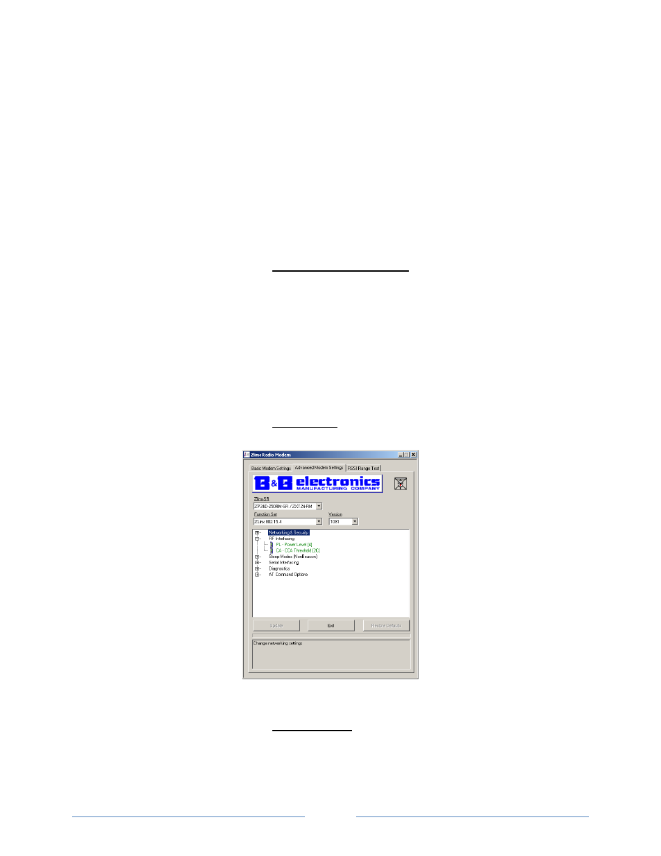
RF Interfacing:
Used to change RF interface options.
Figure 5-32 RF Interfacing (ZXT24-RM)
PL – Power Level
: Select/Read transmitter output power. This is a pull
down option. Selections are:
0 – 10dBm (Lowest)
1 – 12dBm (Low)
- USOPTL4DR-LS - Datasheet (2 pages)
- ZXT9-IOA-KIT - Manual (75 pages)
- ADAM-6066 - Manual (272 pages)
- 855-11619--57 - Datasheet (2 pages)
- 851-10904 - Datasheet (2 pages)
- SS-BLT-100PR - Quick Start Guide (1 page)
- ISOCON-6 - Datasheet (2 pages)
- I-7060 - Manual (64 pages)
- AMU864 - Datasheet (2 pages)
- 714FX6-SC_ST - Manual (154 pages)
- 422LP25R - Datasheet (2 pages)
- ZP9D-115RM-LR - Manual (54 pages)
- EKI-6311GN-EU - Manual (56 pages)
- ZZ24D-NA(NB,NC,ND)-SR - Quick Start Guide (4 pages)
- ESCLP-100 - Manual (23 pages)
- 806-39753 - Datasheet (1 page)
- 485SD9RJ - Datasheet (1 page)
- 712FX4-SC_ST - Manual (154 pages)
- 850-18610 - Manual (18 pages)
- ESW208 Series - Datasheet (2 pages)
- VESR321_ML_SL - Quick Start Guide (3 pages)
- OP10 - Datasheet (1 page)
- RT3G-300_310_320_330_340-W - Configuration Manual (79 pages)
- EIRHP305-T - Datasheet (2 pages)
- EIRSP1 - Datasheet (1 page)
- 422TTL33 - Datasheet (2 pages)
- 485DRCI - Quick Start Guide (2 pages)
- I-7021_P - Datasheet (2 pages)
- NTSA-CAT5E - Datasheet (2 pages)
- 485COSR - Datasheet (2 pages)
- 855-10619--57 - Datasheet (2 pages)
- UH401SL_2KV - Datasheet (2 pages)
- 105FXE-SC(ST)-15-POE - Manual (19 pages)
- 102MC-FL_SC_ST - Manual (23 pages)
- CBL00302 - Datasheet (1 page)
- 850-18100--27 - Datasheet (2 pages)
- 850-10953-DC - Datasheet (2 pages)
- ESR904 - Datasheet (2 pages)
- 308TX-N - Datasheet (3 pages)
- 422LP25N - Datasheet (2 pages)
- 708FX2-SC_ST - Datasheet (3 pages)
- MESR321_SL_ML - Datasheet (2 pages)
- SL2736-698 - Quick Start Guide (8 pages)
- I-7188E Series - Datasheet (1 page)
- ANT-PAD58-19 - Datasheet (1 page)