Dc characteristics, Oscillator signals: xin, xout – Rainbow Electronics AT76C551 User Manual
Page 75
75
AT76C551
1612D–08/01
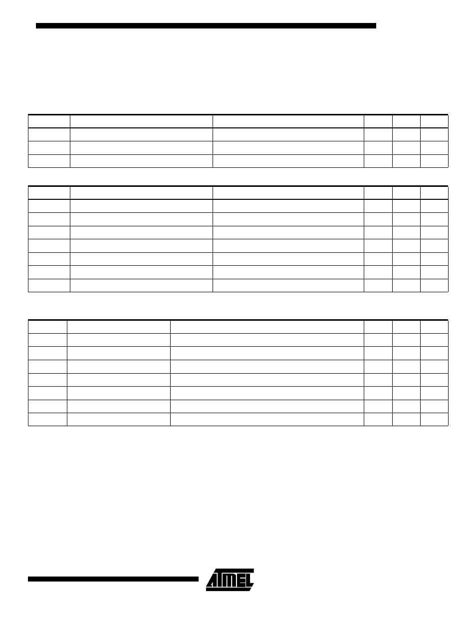
DC Characteristics
The values shown in this table are valid for T
A
= 0
°C to 85°C, V
CC
= 3.3V unless otherwise noted.
Oscillator Signals: XIN, XOUT
Note:
1. XTAL2 must not be used to drive other circuitry.
Table 16. Power Supply
Symbol
Parameter Condition
Min
Max
Unit
V
CC
Power Supply
3.3
V
I
CC
Supply Current
50
mA
I
CCS
Suspended Device Current
200
µA
Table 17. USB Signals: DP, DM
Symbol
Parameter
Condition
Min
Max
Unit
I
LO
High-Z Data Line Leakage
0V < Vin < 3.3V
-10
+10
µA
V
DI
Differential Input Sensitivity
DPx and DMx
0.2
V
V
CM
Differential Common Mode Range
0.8
2.5
V
V
SE
Single Ended Receiver Threshold
0.8
2.0
V
V
CRS
Output Signal Crossover
Except first transition from idle state
1.3
2.0
V
V
OL1
Static Output Low
RL of 15 k
Ω to 3.6V
0.3
V
V
OH1
Static Output High
RL of 15 k
Ω to GND
Table 18. Oscillator Signals: XTAL1, XTAL2
Symbol
Parameter
Condition
Min
Max
Unit
V
LH
XTAL1 Switching Level
0.47
1.20
V
V
HL
XTAL2 Switching Level
0.67
1.44
V
C
X1
Input Capacitance, XTAL1
9
pF
C
X2
Output Capacitance, XTAL2
9
pF
C
12
XTAL1/XTAL2 Capacitance
1
pF
t
SU
Start-up Time
6 MHz, Fundamental
2
ms
D
L
Drive Level
V
CC
= 3.3V, 13 MHz crystal, 120
Ω Equiv. Series Resistor
1
mW