Rainbow Electronics AT76C551 User Manual
Page 16
16
AT76C551
1612D–08/01
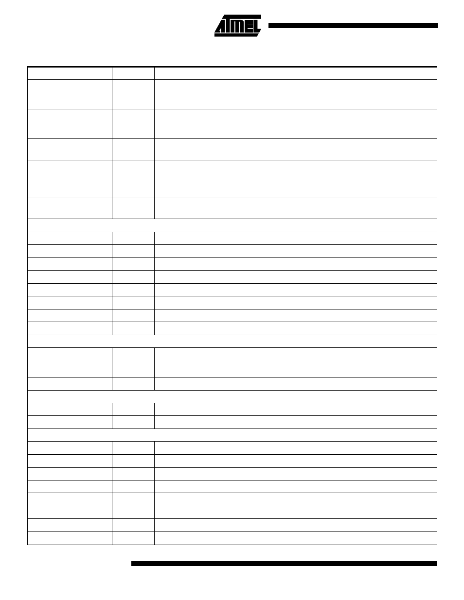
NIOWR
I
I/O Write – Asserted by the host system to indicate to the chip that a write to its I/O address
space is required. The device will not respond until it has been configured for I/O operation
by the system.
NREG
I
Attribute Memory Select – Driven by the host to select between Attribute memory or I/O
space (REG asserted) and Common memory (REG deasserted) in the device and the
PCMCIA card.
NWAIT
O
Extend Bus Cycle – This signal is asserted by the device to delay completion of the access
cycle currently in progress.
NINPACK
O
Input Acknowledge – It is asserted when the BT device is selected and can respond to an
I/O read cycle at the address currently applied on the address bus. It is used by the host to
control the enable of any input buffer between the card and the CPU. It will be inactive
during card configuration.
NIREQ
O
Interrupt Request – Asserted by the chip to indicate to the host that software service should
take place.
UART Interface Pins
U_CTS_
I
Clear to Send
U_DSR_
I
Data Set Ready
U_DTR_
O
Data Terminal Ready
U_RI_
I
Ring Indicator
U_RTS_
O
Request to Send
USART_RX
I
Serial input port
USART_TX
O
Serial output port
U_CD_
I
Carrier Detect
USB Interface Pins
DP
B
Upstream Plus USB I/O. This pin should be connected to CEXT through an external 1.5 k
Ω
pull-up resistor. DPLUS and DMINUS form the differential signal pin pairs connected to the
Host Controller or an upstream Hub.
DM
B
Upstream Minus USB I/O
Analog Voice CODEC Pins
VC_IN
LOG I
Voice input
VC_OUT
LOG O
Voice output
Digital Voice CODEC Pins
ADO
O
Data Transmit
ADI
I Data
Receive
ACLK
O
Master Clock – Out
ABCLK
O
Bit clock – Out
ASYNC
O
Frame Sync – Out
ACLK_IN
I Master
Clock
– In
ABCLK_IN
I
Bit Clock – In
ASYNC_IN
I
Frame Sync – In
Functional Description – Pin Name Order (Continued)
Name
Type
Description