Rainbow Electronics AT76C551 User Manual
Page 67
67
AT76C551
1612D–08/01
US_RTO: Receiver Time-out Register
addr: 700024 hex
R/W
8 bits
• Bits 7..0 – US_RTO[7:0]
This register contains the maximum period, for which the UART can wait before a character
arrives, during the time-out function. This function is disabled when this register is zero. The
value of register US_RTO represents bit periods
Note:
Default Value: 00 hex
US_TTG: Transmitter Time Guard Register
addr: 700028 hex
R/W
8 bits
• Bits 7..0 – US_TTG[7:0]
The value of this register indicates the delay (in bit periods) that an active transmitter has to
interpose between two consecutive character transmissions.
Note:
Default Value: 00 hex
US_MCI Modem Control Inputs
addr: 70002C hex
R
8 bits
• Bit 7 – DSR: Data Set Ready
Active high. This bit is the compliment of the DSR input pin.
• Bit 6 – RI: Ring Indicator
Active high. This bit is the compliment of the RI input pin.
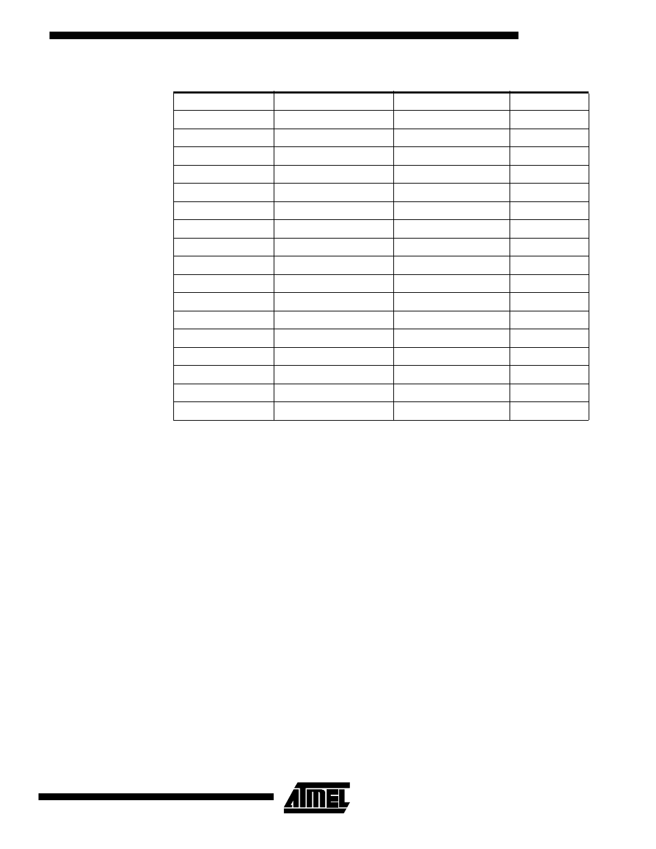
Table 12. Baud Rate Generation Example (Internal UART Clock = 14,76923 MHz)
Baud Rate
US_BM (hex)
US_BL (hex)
Error %
100
24
00
0.16
200
12
00
0.16
400
09
00
0.16
600
06
00
0.16
1200
03
00
0.16
2400
01
80
0.16
4800
00
C0
0.16
9600
00
60
0.16
19200
00
30
0.16
28800
00
20
0.16
38400
00
18
0.16
57.6K
00
10
0.16
115.2K
00
08
0.16
230.4K
00
04
0.16
307.2K
00
03
0.16
460.8K
00
02
0.16
921.6K
00
01
0.16