Two 32-bit timers, Support for different operating frequencies – Rainbow Electronics AT76C551 User Manual
Page 21
21
AT76C551
1612D–08/01
The UART module provides serial asynchronous receive data synchronization, parallel-to-
serial and serial-to-parallel data conversions for both the transmitter and receiver sections.
These functions are necessary for converting the serial data stream into parallel data which is
required with digital data systems.
Synchronization for the serial data stream is accomplished by adding start and stop bits to the
transmit data to form a data character (character orientated protocol). Data integrity is insured
by attaching a parity bit to the data character for control and monitoring. The parity bit is
checked by the receiver for any transmission bit errors.
Two 32-bit Timers
AT76C551 includes two identical system timers. Each system timer is a completely indepen-
dent device. Each has adjustable prescale and preload capable of producing interrupts in a
periodic or one-shot fashion.
Support for
Different
Operating
Frequencies
The AT76C551 chip is able to operate with the following frequencies: 13 MHz, 14.4 MHz, 16.8
MHz and 19.44 MHz. Table 2 shows the correct configuration for each frequency.
Either a crystal or an oscillator can be used. When the OSC_MODE pin is tied to ground the
clock available at the EXT_OSC input is used to drive internal logic. When it is tied to VCC, the
internal clock signal is derived from the XTAL1, XTAL2 pins and associated crystal and
circuitry.
Also a very stable 13 MHz oscillator is required for transceiver operation. This is connected to
the EXT_13_MHZ pin.
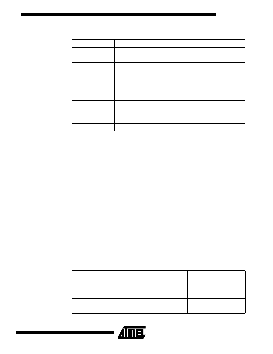
Table 1. Need Table Caption
Baud Rate
Divisor Used
% Error Between Desired and Actual
1200
5000
0
2400
2500
0
4800
1250
0
9600
625
0
19.2K
312
0.16
38.4K
156
0.16
57.6K
104
0.16
115.2K
52
0.16
230.4K
26
0.16
460.8K
13
0.16
921.6K
6.5
0.16
Table 2. Correct Configuration Frequencies
CLK_MODE0
CLK_MODE1
Crystal/Oscillator
Frequency (MHz)
0
0
14.4
0
1
16.8
1
0
19.44
1
1
13