Installation guide, Installation, Product diagrams – Veris Industries H84xx Install User Manual
Page 3: H84xx, H84xxv mounting, H84xxvb(s) mounting, H84xxv, H84xxvb(s), Entrées de tension
Z204046-0J
PAGE 3
©2011 Veris Industries USA 800.354.8556 or +1.503.598.4564 / [email protected]
12115
Alta Labs, Enercept, Enspector, Hawkeye, Trustat, Veris, and the Veris ‘V’ logo are trademarks or registered trademarks of Veris Industries, L.L.C. in the USA and/or other countries.
TM
H84xx
INSTALLATION GUIDE
INSTALLATION
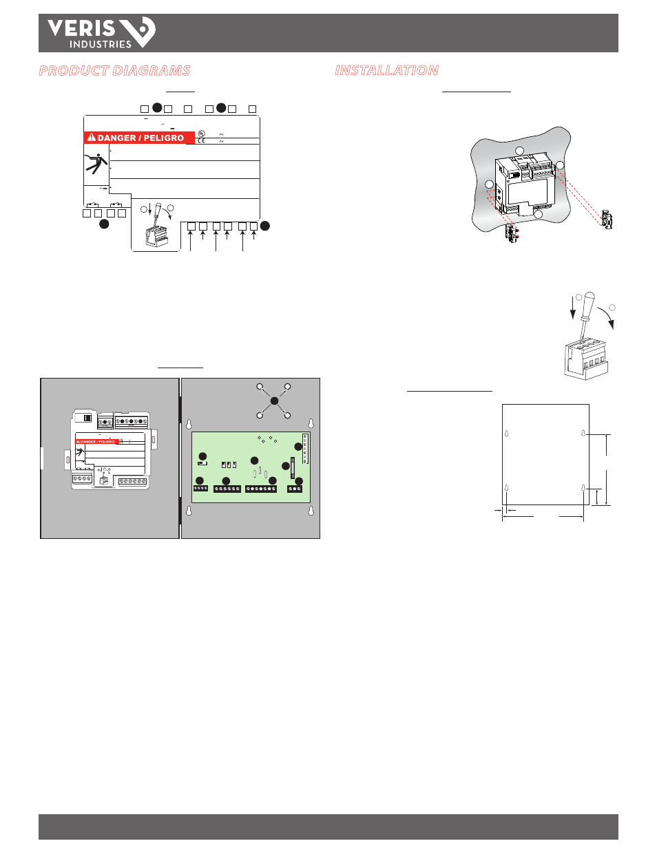
H84xxV Mounting
1. Insert the power meter through a 3.6” x 3.6” (92mm x 92mm) cut-out.
2. Attach the two retainer clips to the
power meter using the retainer slots
at position A or position B.
There are two sets of retainer slots
on the left, right, top and bottom of
the power meter. The first set is for
installation locations thinner than
3 mm (1/8 in.). The second set is for
installation locations 3 to 6 mm (1/8 in.
to 1/4 in.).
NOTE: For use on a flat surface of a protective enclosure (for example, in the USA, use
a NEMA Type 1 rated enclosure or better).
Removing the Connectors:
1. Insert the flat end of a screwdriver into the groove between the
power meter and the connector, as shown in the image.
2. Pull down the screwdriver to remove the connector.
H84xxVB(S) Mounting
Mount the meter box at an appropriate
height allowing for easy viewing of the
display.
Allow a clearance of 1.8” (45mm) of open
space on the left side of the meter to allow
the meter door to open.
PRODUCT DIAGRAMS
H84xxV
1
2
3
4
50/60 Hz / 125-250V 3W
1 10-415V 5 V A
RISQUE D'ÉLECTROCUTION, D'EXPLOSION OU D'ARC ELECTRIQUE
RIESGO DE DESCARG A ELÉCTRICA, EXPLOSIÓN O DESTELLO DE ARCO
HAZARD OF ELECTRIC SHOCK, EXPLOSION OR ARC FLASH
ENTRÉES DE COURANT 1V NOM. / 1.2V MAX.
"CURRENT" INPUTS / ENTRADAS DE CORRIENTE
1-
I
I
1+
3+
2-
2+
I
I
I
3-
I
ENTRÉES DE TENSION
+
1
V
V
2
V
3
N
V
efectuar cualquier trabajo.
Si ces précautions ne sont pas respectés, cela entraÎnera la mort ou des blessures graves.
El incumplimiento de estas precauciones podrá causar la muerte o lesiones serias.
Failure to follow these instructions will result in death or serious injur y.
T urn o f f all power supplying this device and the equipment in which it is installed before
Apague la alimentación del dispositivo y del equipo en el que está instalado antes de
Coupez l'alimentation de cet appareil et de l'équipement dans lequel il est installé avant travaille r .
working on it.
VO LT AGE INPUTS / ENTRADAS DE TENSIÓ N
1
2
KWH PHASE or
KVARH
240V
100mA max
480V L-L 50/60Hz
600V L-L 50/60Hz
R
Z104144-0C
1
7
8
9 10
2
3
4
5
6
14 15 16 17
18 19
Red
White White
White
Black Yellow
1. Control Power
2. Voltage Inputs
3. 1 Volt ‘‘Current” Inputs
4. Pulse Outputs for H8453V, H8463V or RS-485 Output for H8436V, H8437V
H84xxVB(S)
9
J5
J6
J7
N
B
A
L
N
50/60 Hz / 125-250V 3W
1 10-415V 5 V A
RISQUE D'ÉLECTROCUTION, D'EXPLOSION OU D'ARC ELECTRIQU E
RIESGO DE DESCARG A ELÉCTRICA, EXPLOSIÓN O DESTELLO DE ARC O
HAZARD OF ELECTRIC SHOCK, EXPLOSION OR ARC FLAS H
ENTRÉES DE COURANT 1V NOM. / 1.2V MAX.
"CURRENT" INPUTS / ENTRADAS DE CORRIENTE
1-
I
I
1+
3+
2-
2+
I
I
I
3-
I
ENTRÉES DE TENSION
+
1
V
V
2
V
3
N
V
efectuar cualquier trabajo.
Si ces précautions ne sont pas respectés, cela entraÎnera la mo rt ou des blessures graves.
El incumplimiento de estas precauciones podrá causar la muerte o lesiones serias.
Failure to follow these instructions will result in death or se rious injury .
T urn o f f all power supplying this device and the equipment in which it is installed before
Apague la alimentación del dispositivo y del equipo en el que e stá instalado antes de
Coupez l'alimentation de cet appareil et de l'équipement dans l equel il est installé avant travailler .
working on it.
VO LT AGE INPUTS / ENTRADAS DE TENSIÓN
KWH PHASE o r
KVARH
240V
100mA max
480V L-L 50/60Hz
600V L-L 50/60Hz
R
Z104389-0A
1
2
3
7
4
6
8
5
1. RS-485 Terminator Switch (H8436VB/S, H8437VB/S only) *
2. RS-485 Input (H8436VB/S, H8437VB/S) or Pulse Contacts (H8453VB/S, H8463VB/S)
3. 1 Volt “Current” Inputs
4. Voltage Inputs
5. Control Power Input
6. Control Power Fuse — 1/2 Amp, 600VAC
7. Self-Power Connections
8. 600VAC Connections for H84xxVBS or jumper on H84xxVB
9. Studs for 600V transformer — H84xxVBS only
* NOTE: If this unit is the last unit in a daisy chain, then this switch should be in the “on” position.
Otherwise, this switch should remain in the “off” position.
6.5"
165 mm
1.5"
38 mm
7.5"
190 mm
0.5"
13 mm
1
2
B
A
A
B