Installation guide, Dimensions, Safety – Veris Industries H84xx Install User Manual
Page 2
Z204046-0J
PAGE 2
©2011 Veris Industries USA 800.354.8556 or +1.503.598.4564 / [email protected]
12115
Alta Labs, Enercept, Enspector, Hawkeye, Trustat, Veris, and the Veris ‘V’ logo are trademarks or registered trademarks of Veris Industries, L.L.C. in the USA and/or other countries.
TM
H84xx
INSTALLATION GUIDE
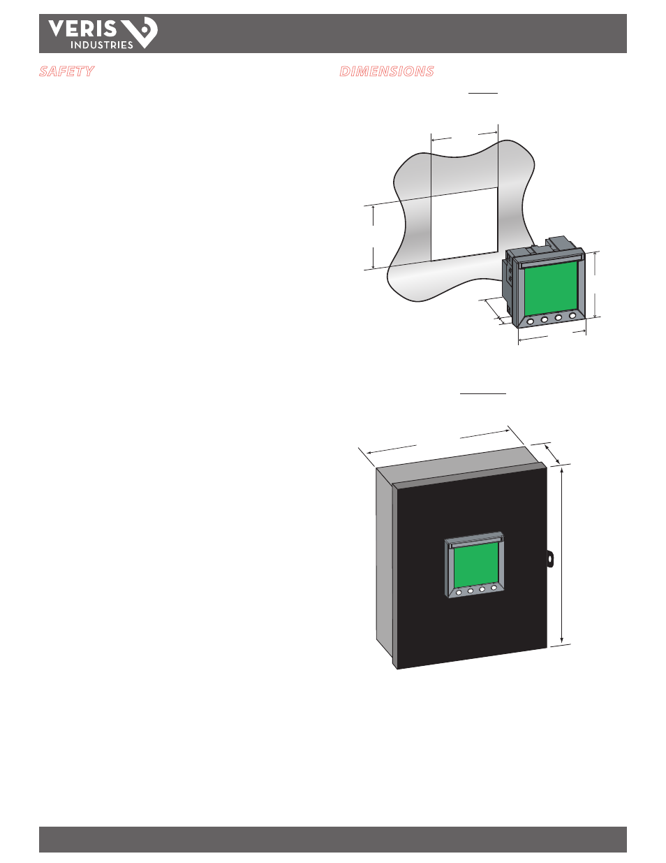
DIMENSIONS
H84xxV
+0.8
–0.0
2"
0.8"
(19 mm)
(50 mm)
3.9"
(96 mm)
3.9"
(96 mm)
(92 mm)
3.6"
(92 mm)
+0.8
–0.0
3.6"
H84xxVB(S)
H8400 SERIES
4.1"
(104 mm)
9.1"
(242 mm)
8.3"
(210 mm)
NOTE: Recommended distance from left side of box to another object is 1.8” (45 mm) to allow
meter door to open.
SAFETY
HAZARD OF ELECTRIC SHOCK, EXPLOSION, OR ARC FLASH
• Only qualified electrical workers should install this equipment. Read
entire instructions before performing this work.
• Before performing visual inspections, tests, or maintenance on this
equipment, disconnect all sources of electric power. Assume that all
circuits are live until they have been completely de-energized, tested,
and tagged. Pay particular attention to the design of the power system.
Consider all sources of power, including the possibility of backfeeding.
• Turn off all power supplying the power meter and the equipment in which
it is installed before working on it.
• Always use a properly rated voltage sensing device to confirm that all
power is off.
• Apply appropriate personal protective equipment (PPE) and follow safe
electrical work practices. In the USA, see NFPA 70E.
• Qualified persons performing diagnostics or troubleshooting that require
electrical conductors to be energized must comply with NFPA 70 E -
Standard for Electrical Safety Requirements for Employee Workplaces and
OSHA Standards - 29 CFR Part 1910 Subpart S - Electrical.
• Before closing all covers and doors, carefully inspect the work area for
tools and objects that may have been left inside the equipment.
• Use caution while removing or installing panels so that they do not
extend into the energized bus; avoid handling the panels, which could
cause personal injury.
• NEVER bypass external fusing.
• NEVER short the secondary of a potential transformer.
• Before performing Dielectric (Hi-Pot) or Megger testing on any
equipment in which the power meter is installed, disconnect all input
and output wires to the power meter. High voltage testing may damage
electronic components contained in the power meter.
• Install the power meter in a suitable electrical and fire enclosure.
Failure to follow these instructions may result in death or serious
injury
.
Always observe all National and Local Codes during installation
of this product.
Mount the box on a solid surface:
1. For use in a pollution degree 2 or better environment only.
2. Connect appropriate safety earth ground wiring to provided grounding terminal.
3. Disconnect devices: in Europe, provide a switch or circuit breaker rated for a
maximum of 20 amps to disconnect the H84xx from the supply source. Place the
switch or circuit breaker in close proximity to the equipment and within easy
reach of the operator, and mark it as the disconnecting device. The disconnecting
device shall meet the relevant requirements of IEC 60947-I and IEC 60947-3 and
be suitable for the application. In the US and Canada, disconnecting fuse holders
can be used.
4. Provide overcurrent protection for supply conductors with approved current
limiting devices suitable for protecting the wiring but not exceeding 20 Amps.
5. Wiring can be up to 12 AWG (2mm) and rated min. 600V.
6. After installation, close the box and secure with the provided plastic cable tie or
securing screw. A lockout device may also be used for this purpose.