Installation guide, Troubleshooting, H84xx – Veris Industries H84xx Install User Manual
Page 29
Z204046-0J
PAGE 29
©2011 Veris Industries USA 800.354.8556 or +1.503.598.4564 / [email protected]
12115
Alta Labs, Enercept, Enspector, Hawkeye, Trustat, Veris, and the Veris ‘V’ logo are trademarks or registered trademarks of Veris Industries, L.L.C. in the USA and/or other countries.
TM
H84xx
INSTALLATION GUIDE
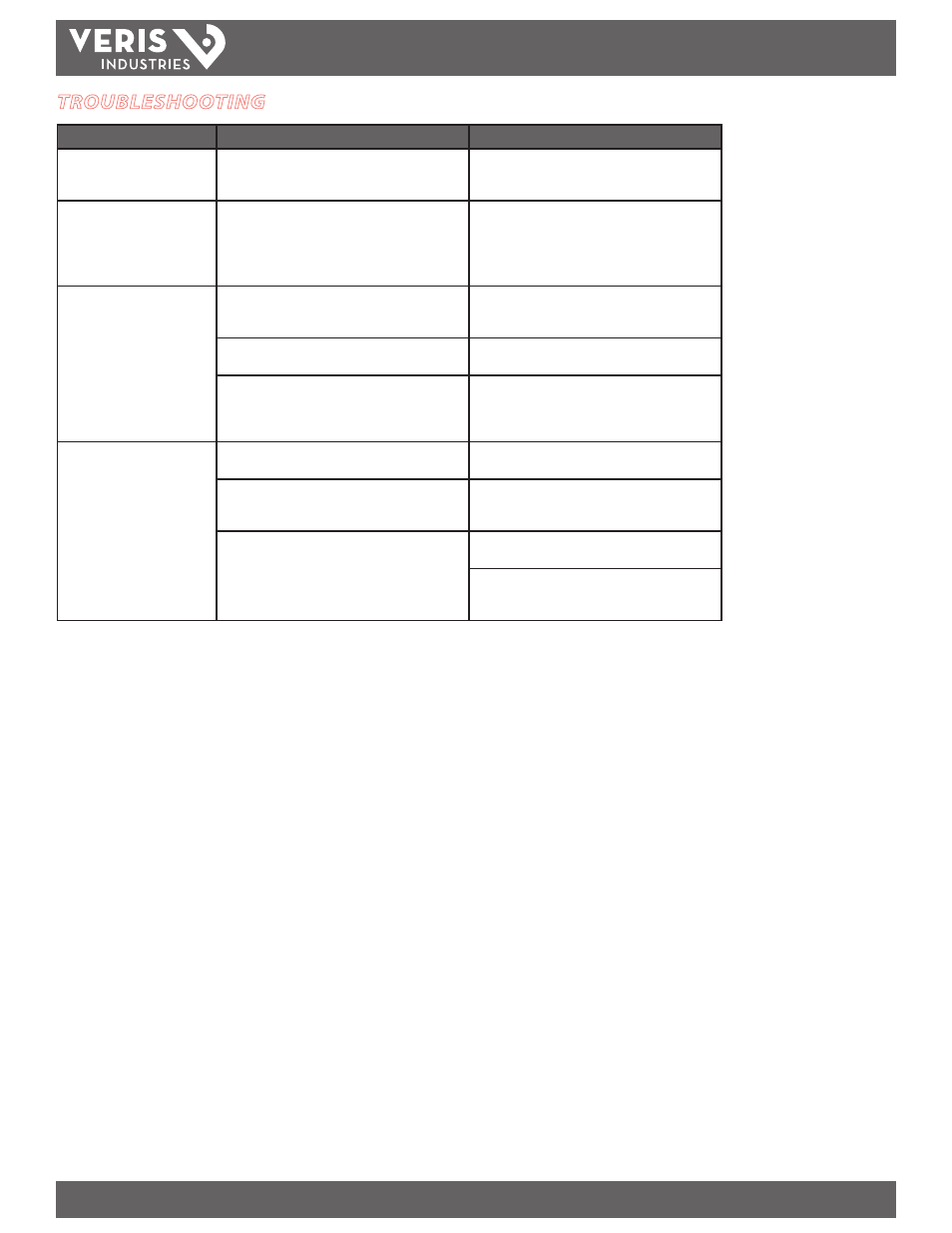
TROUBLESHOOTING
Problem
Cause
Solution
The maintenance wrench icon
appears in the power meter
display.
There is a problem with the inputs to the power meter.
Go to DIAGN>HELTH (MAINT). The error messages
describe the problem. See the Diagnostics section
(page 16) for details.
The display is blank after applying
control power to the meter.
The meter is not receiving adequate power.
Verify that the meter control power (terminals 1 and 2)
are receiving the necessary voltage. See the Control
Power wiring diagram (page 9).
Verify that the LED is blinking.
Check the fuse.
The data displayed is inaccurate.
Incorrect setup values
Verify the values entered for power meter setup
parameters (CT and PT ratings, system type, nominal
frequency, etc.). See the Setup section (page 13).
Incorrect voltage inputs
Check power meter voltage input terminals to verify
adequate voltage.
Power meter is wired improperly.
Check all CTs and PTs to verify correct connection to the
same service, PT polarity, and adequate powering.
Check shorting terminals, if used. See the Wiring
Diagrams (pages 6-8) section for more information.
Cannot communicate with power
meter from a remote personal
computer.
Power meter address is incorrect.
Verify that the meter is correctly addressed (see Setup
section).
Power meter baud rate is incorrect.
Verify that the baud rate of the meter matches that of
all other devices on its communications link (see Setup
section).
Communications lines are improperly connected.
Verify the power meter communications connections
(see the Communications section).
Verify the terminating resistors are properly installed on
both ends of a chain of units. Units in the middle of a
chain should not have a terminator.