Installation guide – Veris Industries H8822 Install User Manual
Page 9
VERIS INDUSTRIES
™
H8822
INSTALLATION GUIDE
ZL0056-0C
PAGE 9
©2010 Veris Industries USA 800.354.8556 or +1.503.598.4564 / [email protected]
06101
Alta Labs, Enercept, Enspector, Hawkeye, Trustat, Veris, and the Veris ‘V’ logo are trademarks or registered trademarks of Veris Industries, L.L.C. in the USA and/or other countries.
Click the Configure button at the bottom of the page. The page will be displayed
2.
again, however the device name and alarm level fields will allow editing. Type in a
name for the device in the space provided at the top of the page. The name should
describe the purpose or location of the IO module. For device 250, you may want
to use the name “internal IO”
For each input that you wish to use, click the “Config Point” button to the right of
3.
the input.
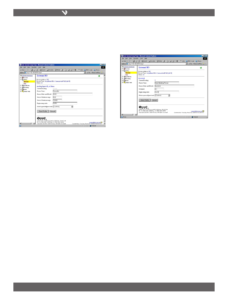
The analog input configuration requires several options. The input mode will
4.
control how the input functions. This includes measuring voltage, current,
resistance, pulse, or runtime. Use the dropdown menu to select the mode that is
appropriate for your sensor. The input configuration must be completed for each
input that is in use.
Sensor Name: Change this to describe the input. This can be anything you
wish, such as “Indoor Temperature.”
Input Mode: Select from one of the following: Voltage 0-10V, Current 4-20
mA, Resistance, Pulse, or Unconfigured.
Sensor Make and Model: This entry is a space for the model number of the
sensor. It is only used for reference.
Sensor Minimum Range: All analog sensors have min/max range values. For
example, a temperature sensor may have a range of 50 to 95 degrees F. Enter
the low range number here.
Sensor Maximum Range: Enter the high range value of the analog sensor
here.
Pulse Multiplier: For pulse mode inputs, this option specifies the multiplier
for the input.
Pulse Rate: For most units, this feature is an automatic rate field. For KWH
points, the rate is KW.
Engineering Units: Enter the units of measure, i.e., degrees F, %RH, etc.
After saving the sensor profile, the device configuration page will appear again.
5.
The input values should now be scaled correctly and the names will be updated
to your new configuration. You may wish to set any alarm thresholds required or
check the “Console” checkbox for any data points that should be displayed on the
LCD console.
Click the “Advanced” button in the lower right corner of the page. For the H8822
6.
onboard IO, there are several options.
After returning to the device configuration page, click “Save” at the bottom of the
7.
page to return to the device display.
Troubleshooting Modbus Devices
If the device you have attached does not appear in the Modbus device list, check the
following:
Verify the + (red), - (black), and Shield connections are correct on all
•
connections. Look for any connection in the middle of the loop that may
have the wires reversed, or shorted together.
Verify the address settings of every Modbus device. No two devices may
•
have the same address. Note: the AcquiSuite DR H8822 uses the address
250 for the internal IO module. Do not assign this address to any other
Modbus device.
If only one device is not working, try disconnecting all the other devices
•
on the Modbus loop to isolate the problem. If possible, bring the failed
device adjacent to the AcquiSuite DR and attach it with a short stub of
wire to eliminate possible wiring problems. If the AcquiSuite DR can find
a device on the short stub, the problem is probably a wiring related issue
on the RS-485 loop.
Check to verify the Modbus device is supported by the AcquiSuite DR.
•
Usually, the AcquiSuite DR will locate the device and print “Unsupported”
in the device status column if the device is not recognized by the
AcquiSuite DR firmware drivers. In the lower right corner of this screen,
there is a link that will show a list of supported devices. Use this to
verify the Modbus device in question is supported by the AcquiSuite DR
firmware version. If not, check for firmware upgrades online with the
Firmware Update configuration page.