Installation guide, Hardware installation, Veris industries – Veris Industries H8822 Install User Manual
Page 4: H8822
VERIS INDUSTRIES
™
H8822
INSTALLATION GUIDE
ZL0056-0C
PAGE 4
©2010 Veris Industries USA 800.354.8556 or +1.503.598.4564 / [email protected]
06101
Alta Labs, Enercept, Enspector, Hawkeye, Trustat, Veris, and the Veris ‘V’ logo are trademarks or registered trademarks of Veris Industries, L.L.C. in the USA and/or other countries.
hardware installation
1. Unpack materials and verify all required components are available.
2. Mount the AcquiSuite DR on the wall or other appropriate location.
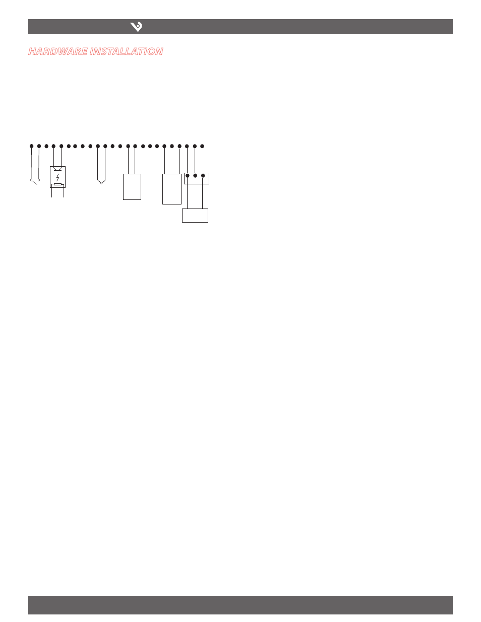
3. (optional) Connect any analog or pulse output sensors you may have. For analog
sensors, 0-10V or 4-20mA sensor types are allowed. The combined power
consumption of all the analog sensors attached to the AcquiSuite DR must not
exceed 200mA. If more current is required, use an external power supply as shown
in the wiring diagram shown below.
4. (optional) Connect the Modbus network loop as shown in the wiring diagram.
Follow the manufacturer’s instructions for installing and powering the Modbus
devices. Verify that the Modbus address settings are unique for each device (i.e.,
no two devices with the same address) and power up the device. Connect each
device in the chain by “daisy-chaining” the devices together. Observe + and -
polarity on the Modbus devices.
Note: Low Voltage analog, pulse, and RS485 wiring that enters electrical
panels must have a minimum insulation rating that exceeds the voltage
inside the panel. In addition, other regulations may apply; consult the
building codes in your area prior to installation.
Note: Some Modbus devices do not use the same label notation as the
AcquiSuite DR.
Note: The AcquiSuite DR H8822 internal IO module (analog and pulse inputs)
uses Modbus address 250, and will show up in the Modbus device count as a
single Modbus device. Additional H8923-4 IO modules may be added to the
Modbus loop as needed.
5. Power-up and diagnostics: Attach the power supply to the power input jack on
the AcquiSuite DR, and plug the power brick into a wall outlet. The power brick
should be in a location that is accessible for connection and disconnection. After
power is applied, the green alive light in the upper right of the AcquiSuite DR
should come on and the LCD display will display a series of diagnostic screens
ending with the following message on the LCD display (this boot sequence may
require up to 20 seconds to complete):
AcquiSuite Ready
This indicates that the AcquiSuite DR has loaded properly and is ready for
configuration and connection to the network and sensors. If the “power” light does
not come on or the LCD display does not cycle to the above screen, verify that the
power cord is plugged in. If after cycling the power the unit still does not power up
(or if an error message appears in the LCD display) contact technical support. After
the H8822 has been powered up for a minute, the yellow RS485 LED should blink
slowly once per second during normal operation. Contact closure on pulse inputs will
cause the red pulse LED to blink. Verify each pulse input is functioning properly by
observing the pulse status LEDs.
- +
2-Wire
4-20mA
GND
Input 1
+24V
GND
Input 2
+24V
GND
Input 3
+24V
GND
Input 4
+24V
GND
Input 5
+24V
GND
Input 6
+24V
GND
Input 7
+24V
GND
Input 8
+24V
Dry
Contacts
Thermistor
Opto-isolator
- out +
3-Wire
0-10V
4-20mA
- out +
-
+
External
Power Supply
Modbus TX/RX: The Modbus TX and RX LEDs blink to indicate data on the
•
RS485/Modbus loop. The RX LED blinks only when data is received by the
AcquiSuite
Modem RTS: the modem is being monitored or operated by the
•
AcquiSuite DR, off when the modem is idle. This LED will be on when a
dialout call is in progress, or when dialin is enabled and waiting for an
inbound call.
Modem CD: the modem has a carrier connection to a remote system.
•
Modem TX/RX: data is being sent or received on the modem.
•
Alive: blinks once per second while the system is operating correctly.
•
Inputs 1-8: in pulse mode, the LED is on when contacts are closed. In
•
analog 4-20mA and 0-10V mode, the LED blinks quickly (2hz) to indicate
an input error alarm.
6. Verify connected devices: To verify that the Modbus devices are installed and
reporting correctly, use the Modbus status utility on the AcquiSuite DR™ server. To
do this test, follow these steps:
A. Press and release the menu (top) button on the AcquiSuite DR. The
following will appear on the LCD display:
Main Menu
TCP/IP Config
B. Press the menu (top) button several more times until the LCD display shows
the following message:
Main Menu
Modbus Status
C. Press the select (bottom) button on the server and the unit will begin the
diagnosis of the Modbus loop. After the check is completed, the unit will
display the following message:
X devices OK
X fail, X new
D. Verify that the number of devices located by the server (the total of OK, fail
and new) matches the number of devices actually installed and connected.
For a first time installation, all devices should appear as “new." The AcquiSuite
DR H8822 Internal IO (pulse and analog inputs) appear as one device in this
list. (Note: A “device” is the Modbus connected device, not necessarily the
sensor. For example, an H8923-4 I/O module with 4 sensors connected is only
one modbus device, not four) For further information on the LCD console,
please review the console section of this manual.
E. The AcquiSuite DR completes a background scan for new Modbus devices
every 2-5 minutes. Increasing the RS485 Modbus timeout may increase the
time required to detect new devices. If the Modbus devices are connected
after the server is booted up, the devices may not appear on the screen for
several minutes. In the worst case, allow up to 5 minutes for the AcquiSuite
DR to locate all the connected devices.
F. If all devices are reporting properly, it is now time to connect the server to
the network or phone line for remote reporting and configuration.