Installation guide, Modbus – Veris Industries H8822 Install User Manual
Page 8
VERIS INDUSTRIES
™
H8822
INSTALLATION GUIDE
ZL0056-0C
PAGE 8
©2010 Veris Industries USA 800.354.8556 or +1.503.598.4564 / [email protected]
06101
Alta Labs, Enercept, Enspector, Hawkeye, Trustat, Veris, and the Veris ‘V’ logo are trademarks or registered trademarks of Veris Industries, L.L.C. in the USA and/or other countries.
modbus
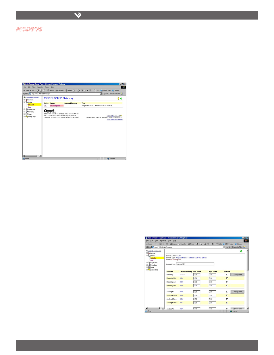
Modbus Device List
The AcquiSuite DR automatically searches for Modbus devices on the RS-485 serial
loop. The Modbus Device List page will show a listing of all the currently detected or
configured devices the AcquiSuite DR has found. The device list will show the Modbus
address number, status (OK, Error, Alarm, Unconfigured), the device name (user
specified), and the device identification string.
Click on the Modbus address number for any of the devices for specific device details.
Note: not all Modbus devices are supported by the AcquiSuite DR. If a device
appears in the list with “Unsupported” in the status column, you may
need to upgrade the firmware on the AcquiSuite DR to access the device.
At the bottom right corner of the device list page, a link is shown that will
enumerate all the supported Modbus devices in the installed version of the
firmware. Use the System/Firmware update page to check for newer versions
of the firmware. The Veris.com website faq also has a list of supported
Modbus devices.
Device Details
The Device Detail page will show a list of all the meter data points, alarm settings and
console options. The data point names for most devices are automatically entered.
Some devices such as the H8923-4 IO module have generic inputs, and will be labeled
as “pulse input #1”. At the top of the page, the status of the device is shown. This
usually reports “ok” however it can include error information if the device is not
responding properly. A list of device errors is available in the log file details section of
this manual. At the bottom of the page, several buttons are present.
Done: returns you to the device list page.
Log File: will display a tabular view of the most recent data in the current log
file. Use the log file export page for complete log data access.
Configure: This button will allow you to change the device parameters such as
the name, alarm and console settings.
Device Configuration
Clicking the “Configure” button from the Device Details page will refresh the screen
with the same information, however the device name, alarm settings and console
checkbox will be available.
Device Name: This field allows you to specify a name for the device such
as “main building power” or other useful name to indicate the location or
function of the device. A name must be assigned to a device before the
AcquiSuite DR will log data for it.
Low Alarm, High Alarm: Specify a threshold for the alarm. If the data point is
recorded below the Low Alarm, or above the High Alarm levels at the time a
log entry is taken, the point will be considered in an alarm state.
Console: Checking this checkbox will cause the AcquiSuite DR to display this
data point on the LCD console. Multiple data points are rotated about every
10 seconds. The values on the LCD console are updated when the next log
interval occurs.
Point Config: Some devices have configurable point features. The H8923-4 IO
module has 4 pulse and 4 analog inputs that require additional configuration
as detailed in the next section. The H663/704 BCM product only requires
the circuit breaker name in this menu. Most device points are automatically
configured, and this option may not be displayed.
Advanced: At the lower right corner of the page, an advanced configuration
button may be present depending on the Modbus device features.
Advanced Configuration Options
The advanced configuration page contains special options specific to the device you
are configuring. For the H8923-4 IO module, you may specify the pulse rate speed
that the pulse inputs will work at, as well as review the 4-20mA/0-10V input status.
On power meters, the CT size and orientation options may be present. The device
serial number and other specific parameters will be displayed if available.
Internal IO Configuration
The H8822 AcquiSuite DR provides 8 multipurpose inputs on board. The onboard IO
inputs will always be device 250 in the device list.
Click on the device number 250 in the device list. A page showing the device
1.
inputs will be presented. Each input has 5 lines on this page. Analog inputs
have one line each for an instantaneous, min, max and average value. Pulse
inputs have a line for the accumulated value, rate, runtime and status.