Figure 2, Dilution unit dil-1/h – M&C TechGroup DIL-1_(H) Operator's manual User Manual
Page 9
9
Gas sampling and gas conditioning technology
2-1.1.7.6-ME
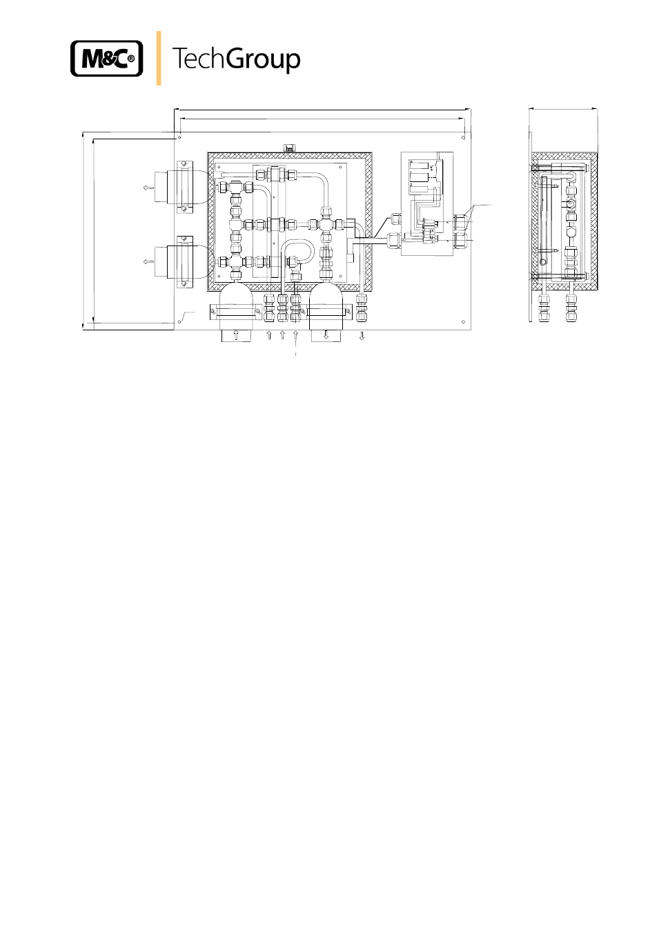
450
430
300
280
** Connection tube 8x1mm
* Connection tube 6x1mm
Bypass-
gas in*
Sample in*
(non diluted)
Ø 6
Sample out**
(non diluted)
Dilution
gas in*
Testgas
in*
Depression-
manometer*
Option I
Bypass out*
(undiluted)
Alarm-Kontakt
230V,50Hz
(115V,60Hz)
Temp.-min
Netz
Tsoll
Tu<-30°C
0-180°C
To>+30°C
Reset
PG 13,5
104
Option II
Sample out*
(undiluted)
Figure 2
Dilution unit DIL-1/H
The M&C dilution units DIL-... are mounted on a plate for wall mounting. The operating temperature of
the non heated version DIL-1 is the ambient temperature. Version DIL-1/H is heated up to 180 °C and
is equipped with a heat insulated cover (Version for 320 °C on request).
The temperature is regulated by an integrated capillary thermostat, adjustable from 0-180 °C, includ-
ing an excess temperature limiter and a low temperature alarm. (Optional: Temperature sensor PT100
or thermocouple “”K” for external temperature controller on request)
The connection of the heated lines is made without cold bridges into the heated part. Before the dilu-
tion gas enters the dilution unit, it is heated up to the operating temperature via a gas pre-heater. In
order to protect the dilution part against contaminations, internal protective filters are installed for the
sample gas and the dilution gas stream.
For calibration of the analyser, test gas can be feeded via the integrated test gas connection. A preci-
sion pressure controller with manometer is used for adjustment of the necessary dilution gas admis-
sion pressure. Via a vacuum pressure gauge, the function of the dilution injector is controlled. Both,
pressure controller and pressure gauge have to be ordered separately. Two versions are available:
Set -A (-A1) for direct mounting on the mounting plate and control panel type -S (-S1) for external 19"
rack mounting. A shut-off valve and a flowmeter for adjustment of the calibration gas are included in
the version
–S (-S1).
The dilution unit can realize dilution ratios of 10:1 to 500:1. In case of high dilution ratios, a respective
small quantity of gas is sampled from the process. Optionally, a bypass injector
–B (Option I) is avail-
able in order to shorten the response time in case of operation with atmospheric pressure. The bypass
injector is integrated right in front of the dilution unit.
The pressure regulator versions
–A / -S include a pressure regulator with manometer for the dilution
gas as well as a manometer for control of the depression on the critical orifice.
In case of option I, an
additional pressure controller with manometer is included in both mounting versions -A1 / -S1.
The construction of the dilution unit guarantees easy operation and maintenance being independent
from process temperature.