Figure 5, Dilution unit dil-1/h with control panel, S or -s1 – M&C TechGroup DIL-1_(H) Operator's manual User Manual
Page 12: Figure 6, Dilution unit dil-1/h with set -a or -a1, Steuer panel, Figure 6 dilution unit dil-1/h with set -a or -a1
12
Gas sampling and gas conditioning technology
2-1.1.7.6-ME
450
430
300
** Connection tube 8x1mm
* Connection tube 6x1mm
Bypass
gas IN*
Sample IN*
(undiluted)
Ø
Sample
OUT**
(undiluted)
Dilution gas
IN*
Testgas
IN*
Depression
manometer*
Option II
Sample out*
(undiluted)
(undiluted)
Bypass out*
Option I
104
Alarm-Kontakt
230V,50Hz
(115V,60Hz)
Temp.-min
3
2
1
L
N
8
6
7
4
5
L
’
Netz
Tsoll
Tu<-30°C
0-180°C
To>+30°C
Reset
PG 13,5
open
482
(84TE)
132 (3HE)
Option: Bypass
1,0
0,0
6,0
5,0
Bypass-Injector
3,0
2,0
4,0
Steuer panel
Dilution gas
1,0
0,0
6,0
5,0
3,0
2,0
4,0
open
-0,4
0,0
Injector
Depression
-1,0
-0,8
Test gas
-0,6
-0,2
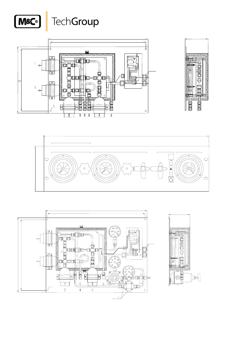
Figure 5
Dilution unit DIL-1/H with control panel
–S or -S1
Option
500
480
370
350
Ø 6
Sample in*
(undiluted)
Test gas in*
Sample out**
(diluted)
Option I
Bypass out*
(undiluted)
Dilution gas
in*
104
PG 13,5
0-180°C
Tu<-20°C
To>+20°C
Tsoll
Reset
Power
230V 50Hz
115V 60Hz
Alarm contact
Temp.-min
Option II
Sample out*
(undiluted)
* Tube connection 6 x 1mm
** Tube connection 8 x 1mm
Figure 6
Dilution unit DIL-1/H with set -A or -A1