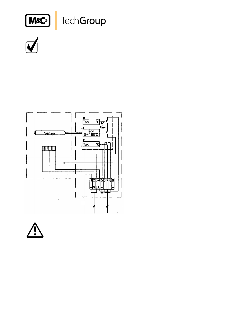
Figure 10, Electrical connection for dil-1/h – M&C TechGroup DIL-1_(H) Operator's manual User Manual
Page 21
21
Gas sampling and gas conditioning technology
2-1.1.7.6-ME
N O T E !
For the erection of power installations with nominal voltages of up
to 1000V, the requirements of VDE 0100 and its associated stan-
dards and specifications must be observed.
A main switch must be provided externally.
The supply circuit of the unit must be equipped with a fuse with the
correct rating (over current protection); the electrical details see
technical data.
Remove cover of the connection box.
Insert the mains cable (min. 3 x 1,5 mm
2
) through the cable gland and connect to the appropriate
terminals.
Insert the signal cable (low temperature alarm) through the cable gland and connect to the appro-
priate terminals (contact position T
u
shows alarm event).
Screw cover back in place.
Mains 230V 50Hz
or 115V 60Hz
Alarm outlet
1
2
1
2
+30
-30
800 W
Figure 10
Electrical connection for DIL-1/H..
W A R N I N G !
We recommend the use of temperature resistent cables!
- SP10 Operator's manual (14 pages)
- N9 KP18 Operator's manual (21 pages)
- SP2000_20SS 150 Data sheet (3 pages)
- SP3100 Data sheet (6 pages)
- PSP4000-H _C _T Data sheet (4 pages)
- SP2200-H_C_I_BB_F Data sheet (2 pages)
- SP35-H... for gas sample probe SP2000-H... Data sheet (2 pages)
- FP-BF Data sheet (2 pages)
- SP3200 Operator's manual (28 pages)
- FPF-0,1 Operator's manual (2 pages)
- PSS-10_1 Operator's manual (23 pages)
- CSS-V2 Data sheet (3 pages)
- PMA 50 EEX Operator's manual (48 pages)
- MP30 Operator's manual (18 pages)
- SP2600-H_C_I_BB_F_0,1GF190 Data sheet (3 pages)
- SR25.1_Ex Operator's manual (22 pages)
- PMA 10S Operator's manual (27 pages)
- CSS-M_W Data sheet (3 pages)
- PAS-500 Operator's manual (20 pages)
- SP2000H320_DIL... Data sheet (3 pages)
- SP3200 Data sheet (6 pages)
- FA-1_2_3,bi Operator's manual (24 pages)
- SR25 Data sheet (2 pages)
- SP3000 Data sheet (4 pages)
- PAS Series Data sheet (2 pages)
- CG Series Data sheet (2 pages)
- ECP 20-2 Data sheet (3 pages)
- MP30-EX Data sheet (2 pages)
- PSP4000-H_C_T Operator's manual (24 pages)
- DIL-U Data sheet (2 pages)
- ADS-So Data sheet (2 pages)
- VC-2-SL Operator's manual (18 pages)
- ECM-ExII Operator's manual (39 pages)
- MP12 Operator's manual (17 pages)
- FPF+ Data sheet (2 pages)
- KS 2.Ex Operator's manual (17 pages)
- PMA 50 EEX Data sheet (3 pages)
- PMA 10S Data sheet (3 pages)
- Gas Sample Probes Series SP Data sheet (2 pages)
- BA-C Operator's manual (16 pages)
- MV3_2-H Series Operator's manual (18 pages)
- VC-2-SL Data sheet (3 pages)
- FM-200K-H_FA Operator's manual (16 pages)
- SP 30-H.._EX2 Operator's manual (16 pages)
- SP2006-H280_DIL Operator's manual (35 pages)