Figure 11, Extract from the injector data sheet, Figure 12 – M&C TechGroup DIL-1_(H) Operator's manual User Manual
Page 23
23
Gas sampling and gas conditioning technology
2-1.1.7.6-ME
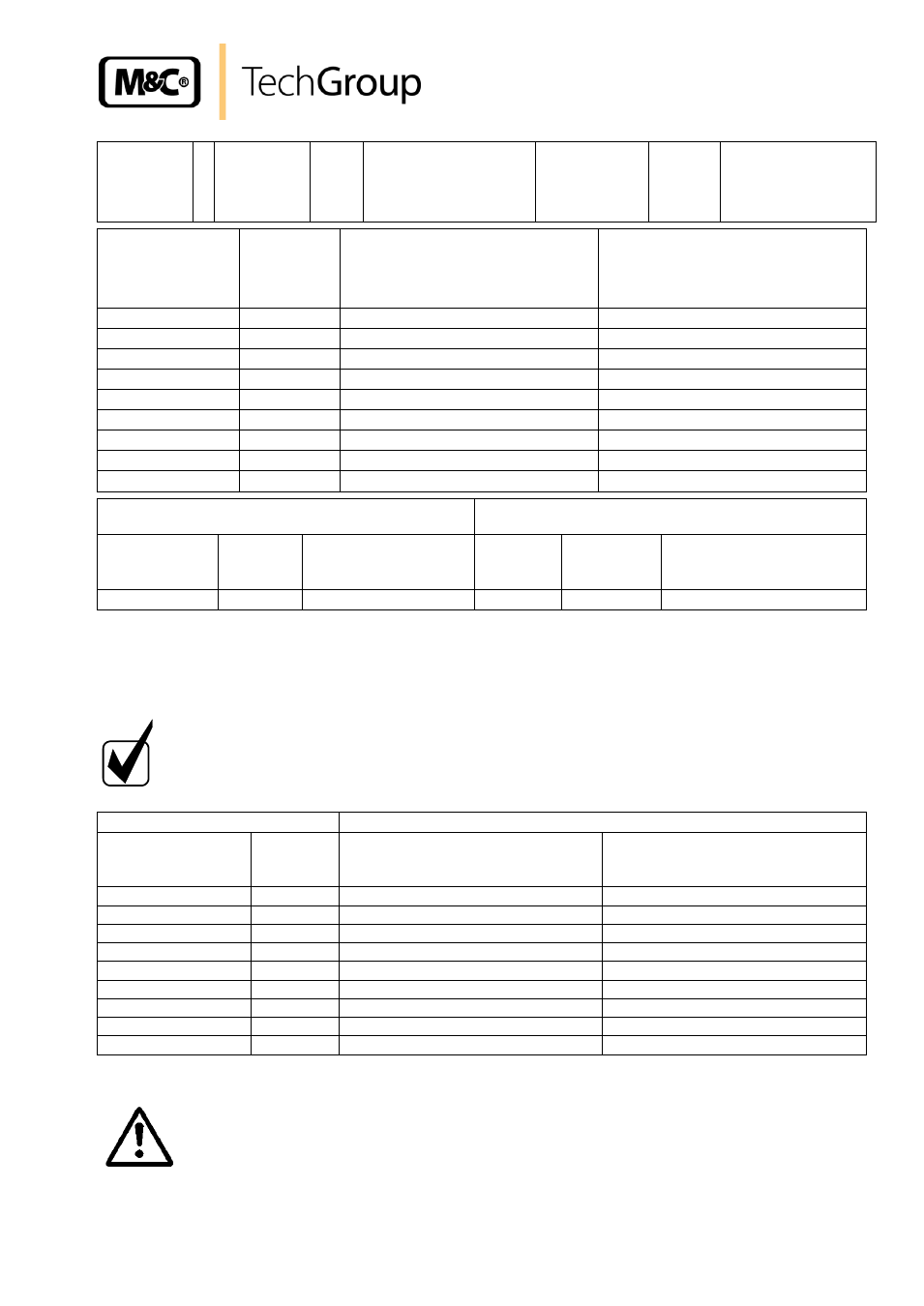
Injektortyp
I
Injektor-Nr.
689
Für Verdünnungs-
system-Nr.
8652/222835
Typ
DIL-1/H-A1
Injector
type
Injector
No.
For dilution system
No.
Type
Betriebsdruck
Operating pres-
sure
[bar]
Durchfluss
Flow
[l/h]
Unterdruck ohne kritische Düse
Vacuum without critical orifice
[bar]
Unterdruck mit kritischer Düse
Vacuum with critical orifice 5,1l/h
[bar]
2,4
415
-0,62
-0,61
2,6
435
-0,65
-0,64
2,8
460
-0,68
-0,67
3,0
490
-0,80
-0,77
3,2
510
-0,79
-0,77
3,4
535
-0,79
-0,77
3,6
560
-0,78
-0,76
3,8
585
-0,77
-0,76
4,0
605
-0,77
-0,75
Überprüfung des Verdünnungsfaktors
Check of the dilution ratio
Messgasdruck atmosphärisch
Sample gas pressure atmospheric
Kritische Düse
Critical nozzle
Verd.gas
Dilution
gas
Verdünnungsgasdruck
Dilution gas pressure
Messgas
Sample
Verdünnung
Dilution
Messwert d. verd. Gases
Meas. value of the dil. gas
5,1 l/h
100% N
2
3,2 bar
100% O
2
100:1
1,0 % O
2
Figure 11
Extract from the injector data sheet
For the operation of an installed bypass injector, the necessary pressure must be set on the pres-
sure regulator (see figure 12).
N O T E !
The attached bypass injector table shows the suction flows at cor-
responding bypass gas pressures for two different process pres-
sures, 1 bar and 0,9 bar absolute (see figure 12).
Bypassgas / Bypass gas
Prozessgas / Sample gas
Betriebsdruck
Operating pressure
[bar]
Durchfluss
Flow
[l/h]
Ansaugvolumenstrom bei 1bar abs.
Suction flow at 1bar abs.
[l/h]
Ansaugvolumenstrom bei 0,9bar
abs.
Suction flow at 0,9bar abs. [l/h]
0,5
110
45
-
1,0
155
115
-
1,5
190
200
65
2,0
235
250
135
2,5
270
300
200
3,0
310
350
250
3,5
355
370
270
4,0
395
390
305
4,5
430
425
350
Figure 12
Suction flow at 0,9 or 1bar abs. in dependence on the bypass gas pressure
W A R N I N G !
In the event of low temperature (failure of the heating) the supply of
dilution gas must be interrupted!