Technical data – M&C TechGroup DIL-1_(H) Operator's manual User Manual
Page 13
13
Gas sampling and gas conditioning technology
2-1.1.7.6-ME
8
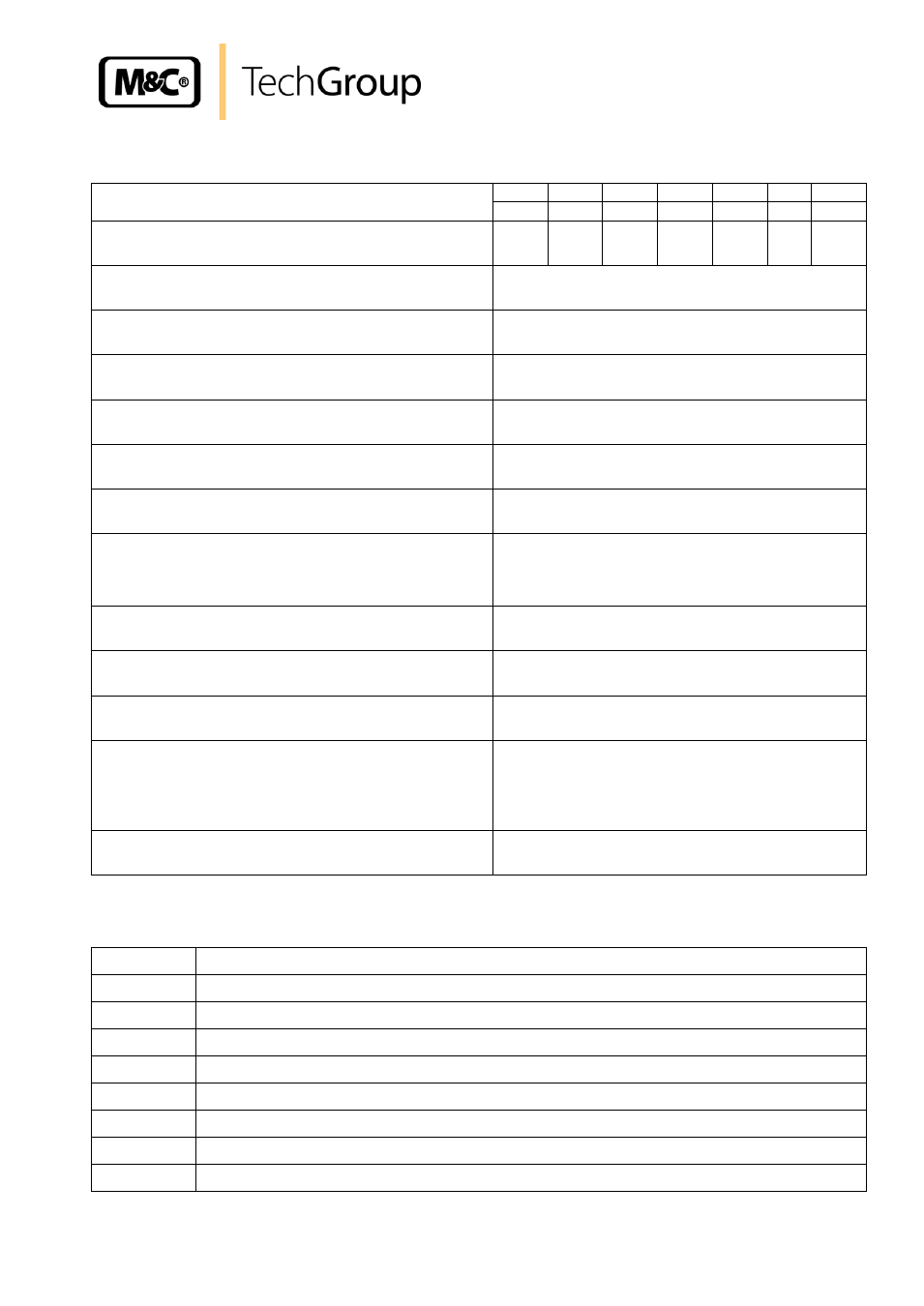
TECHNICAL DATA
Dilution ratios of the critical orifices „a“ to „g“
a
b
c
d
e
f
g
500
200
100
50
30*
20
10:1
Sample flow rate with critical orifices „a“ to „g“
1,4
2,7
5,5
11
19*
28
55l/h
1)
Possibility to adapt the dilution factor
With dilution gas pressure adjustment -5% to +30%
2)
Dilution gas flow rate with injector version I or II
I: 480 - 600 Nl/h, optional II: 1800
– 3000 Nl/h
Dilution gas pressure on inlet of pressure controller
Min. 4,5 bar, max. 16 bar
Bypass injector /B: pressure / Gas consumption / flow
rate
approx. 2 bar : injector gas approx. 300 l/h : sample
gas approx. 150 l/h
Process pressure
0,9 to 2 bar abs. at constant pressure
Fault caused by process temperature variations
No fault, operation independent of process tempera-
ture
Fault caused by process low or over pressure
Influence negligible at pressure changes
≤ 200mbar
and if test gas is given to the probe under process
conditions. Otherwise proportional to pressure
changes.
Fault caused by atmospheric pressure variations
< 1% with a variation of 50 mbar
Material in contact with the sample gas
Stainl. Steel 316Ti, quartz glass, FPM, graphite
Power supply for DIL-1/H
230V 50Hz, (optional 115V 60Hz), 800W
Temperature controller for DIL-1/H
Capillary thermostat adjustable 0-180 °C, with ex-
cess temperature limiter and low temperature alarm
as changeover contact, potentialfree alarm point T30
°C to T
Set
,
contact rating max. 250V 3A~ 0,25A =
Weight
approx. 8 kg
* Standard, others to be indicated along with order, intermediate values possible.
1)
approx at 3 bar dilution gas.
2)
-5%, however not possible wit
h orifice „g“.
Type
M&C Dilution unit DIL-
1/(H) with orifice „e“, dilution ratio 30:1, Standard
DIL-1
Dilution unit non heated
DIL-1/H(a)
Dilution unit electrically heated to 180°C, (a) = voltage 115V 60Hz
Option I
Bypass injector
–B
Option II
Additional sample gas outlet undiluted
DIL-1/..-A
Option: mounting set for dilution unit, 1 pressure controller and 2 manometers
DIL-1/..-A1
Option: mounting set for dilution unit/Bypass injector, 2 pressure controllers and 3 manometers
DIL-1/..-S
Option: control panel with 1 pressure controller, 2 manometers, flowmeter, 2 shut-off valves
DIL-1/..-S1
Option: control panel with 2 pressure controller, 3 manometers, flowmeter, 2 shut-off valves